Laser machining device and laser oscillation control method

a laser and machining technology, applied in the direction of manufacturing tools, soldering devices, auxillary welding devices, etc., can solve the problems of melted or disconnection of optical fibers, and achieve the effect of high laser beam output and good precision

Active Publication Date: 2015-01-22
AMADA CO LTD
View PDF43 Cites 14 Cited by
  • Summary
  • Abstract
  • Description
  • Claims
  • Application Information

AI Technical Summary

Benefits of technology

[0005]On the other hand, for the laser machining device using an optical fiber, a trend for realizing a higher output for a laser beam has been progressed considerably, so that it is made possible for a user to make a variable control of an output of a laser beam arbitrarily from a low output to a high output, according to a material to be machined and a content of the machining. Moreover, there is also a laser machining device for automatically selecting an optimal output from machining conditions such as a material of a work, a thickness of a plate, etc., and appropriately adjusting it even during the machining. Also, as a method for evaluating a detection result of a returning light, a method in which a threshold for an intensity of a detected cladding leaked light is set in advance and it is judged as NG in a case where that threshold is exceeded will be desired most, because a sophisticated computational processing is unnecessary and a device can be configured for a general purpose inexpensively.
[0006]However, in the case where an output of a laser beam is changed, the intensity of the cladding leaked light detected by a sensor will be changed regardless of a presence or absence or a level of a returning light, so that it becomes difficult to make a judgment as to whether a returning light that exerts an adverse effect to the optical fiber is occurring or not in good precision.

Problems solved by technology

Then, in a case where an amount of light of that returning light is large, there is also a concern for resulting in a melting or a disconnection of an optical fiber itself.

Method used


Image

  • Laser machining device and laser oscillation control method
  • Laser machining device and laser oscillation control method
  • Laser machining device and laser oscillation control method

Examples


Embodiment Construction

[0023]The embodiment of the present invention will be described by way of an exemplary embodiment using FIG. 2 to FIG. 9.

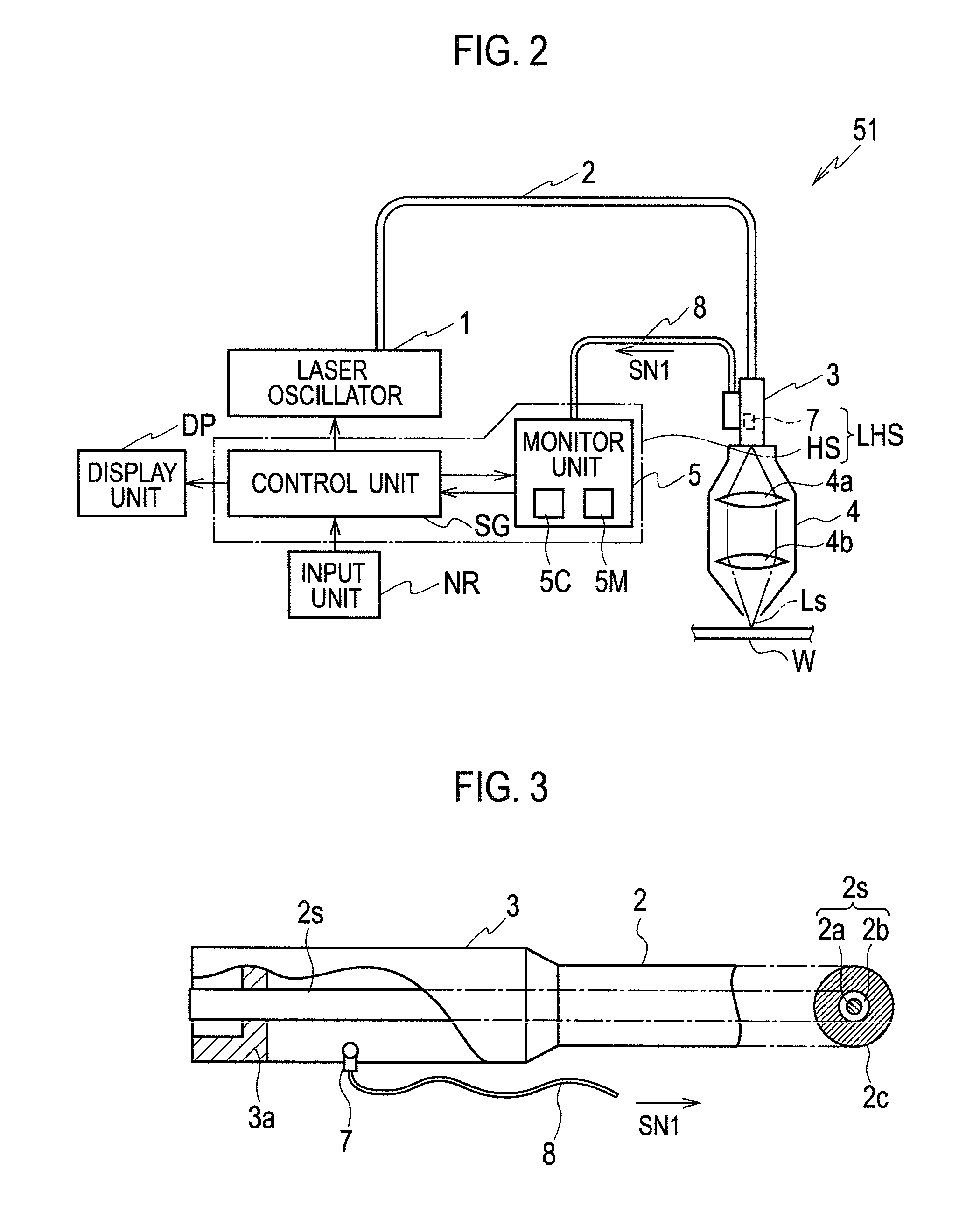
[0024]First, using FIG. 2 and FIG. 2, a configuration of a laser machining device 51 of an exemplary embodiment will be described.

[0025]The laser machining device 51 is a so called fiber laser machining device, and has a laser oscillator 1, an optical fiber 2 for propagating a laser beam oscillated from the laser oscillator 1, a connector unit 3 provided at a tip end portion of the optical fiber 2, a head unit 4 connected to said connector unit 3, for irradiating the laser beam with respect to a work W which is a material to be machined, a control unit SG for controlling an entire device including an operation of the laser oscillator 1, a monitor unit 5 for receiving an output signal from the connector unit 3 and carrying out signal exchanges with the control unit SG, a display (output) unit DP having a speaker device, an image display device and the like for outp...


PUM

PropertyMeasurementUnit
thresholdaaaaaaaaaa
sizesaaaaaaaaaa
thicknessaaaaaaaaaa

Abstract

A laser machining device includes a laser oscillator for oscillating a laser beam to have a variable output according to a machining condition, an optical fiber for propagating the laser beam, a sensor for detecting an intensity of a light leaking from a cladding side face of the optical fiber and outputting a detection signal indicating that intensity, and an oscillation control unit for controlling an operation of that laser machining device based on the detection signal. The oscillation control unit compares a first threshold that is set in correspondence to that output with an intensity or an amount of light obtained from the detection signal, compares a second threshold that is set in correspondence to that output with an intensity or an amount of light obtained from the detection signal, and controls the operation of that laser machining device based on a result of comparing.

Description

TECHNICAL FIELD[0001]The present invention relates to a laser machining device and a laser oscillation control method, and in particular, to one that prevents an occurrence of a defect of an optical fiber caused by a retuning light very well, in a laser machining using an optical fiber.BACKGROUND TECHNIQUE[0002]In a laser machining using an optical fiber, when an irradiated laser beam is reflected by a machining target object and re-entered into a cladding of an optical fiber as a returning light, there is a possibility for burning out a coating layer and the like of an optical fiber. Then, in a case where an amount of light of that returning light is large, there is also a concern for resulting in a melting or a disconnection of an optical fiber itself. For this reason, a technique for detecting a returning light and controlling an operation of a laser oscillator according to its amount of light has been proposed. In the patent document 1, it is described that, in an optical fiber ...

Claims


Application Information

Patent Timeline
Patent Type & Authority Applications(United States)
IPC IPC(8): B23K26/08B23K26/06B23K26/30
CPCB23K26/428B23K26/0626B23K26/0807B23K26/0639B23K26/0648B23K26/032B23K37/006B23K26/08B23K26/02B23K26/064B23K26/082B23K26/707
Inventor FUNAKI, KOJIKAGIWADA, YOSHITO
Owner AMADA CO LTD
Why Eureka
Try Eureka