Optically pumped magnetometer and optical pumping magnetic force measuring method

a magnetometer and optical pumping technology, applied in the field of optical pumping magnetometer and optical pumping magnetic force measurement method, can solve the problems of inability to remove the influence of the size fluctuation the inability to cancel the noise which could have been detected by a difference detection, etc., to reduce the influence of the spin polarization fluctuation and suppress the noise

Inactive Publication Date: 2015-01-22
CANON KK
View PDF2 Cites 51 Cited by
  • Summary
  • Abstract
  • Description
  • Claims
  • Application Information

AI Technical Summary

Benefits of technology

[0013]The present disclosure has been made in consideration of the above problems. The present disclosure provides an optically pumped magnetometer and a

Problems solved by technology

In such optical magnetometers having a single optical axis, there has been a problem that noise which could have been canceled by a difference detection cannot be canceled since the polarization plane of the probe light rotates when a size of a spin polarizat

Method used


Image

  • Optically pumped magnetometer and optical pumping magnetic force measuring method
  • Optically pumped magnetometer and optical pumping magnetic force measuring method
  • Optically pumped magnetometer and optical pumping magnetic force measuring method

Examples


embodiments

[0081]Embodiments of the present invention are described hereinafter.

first embodiment

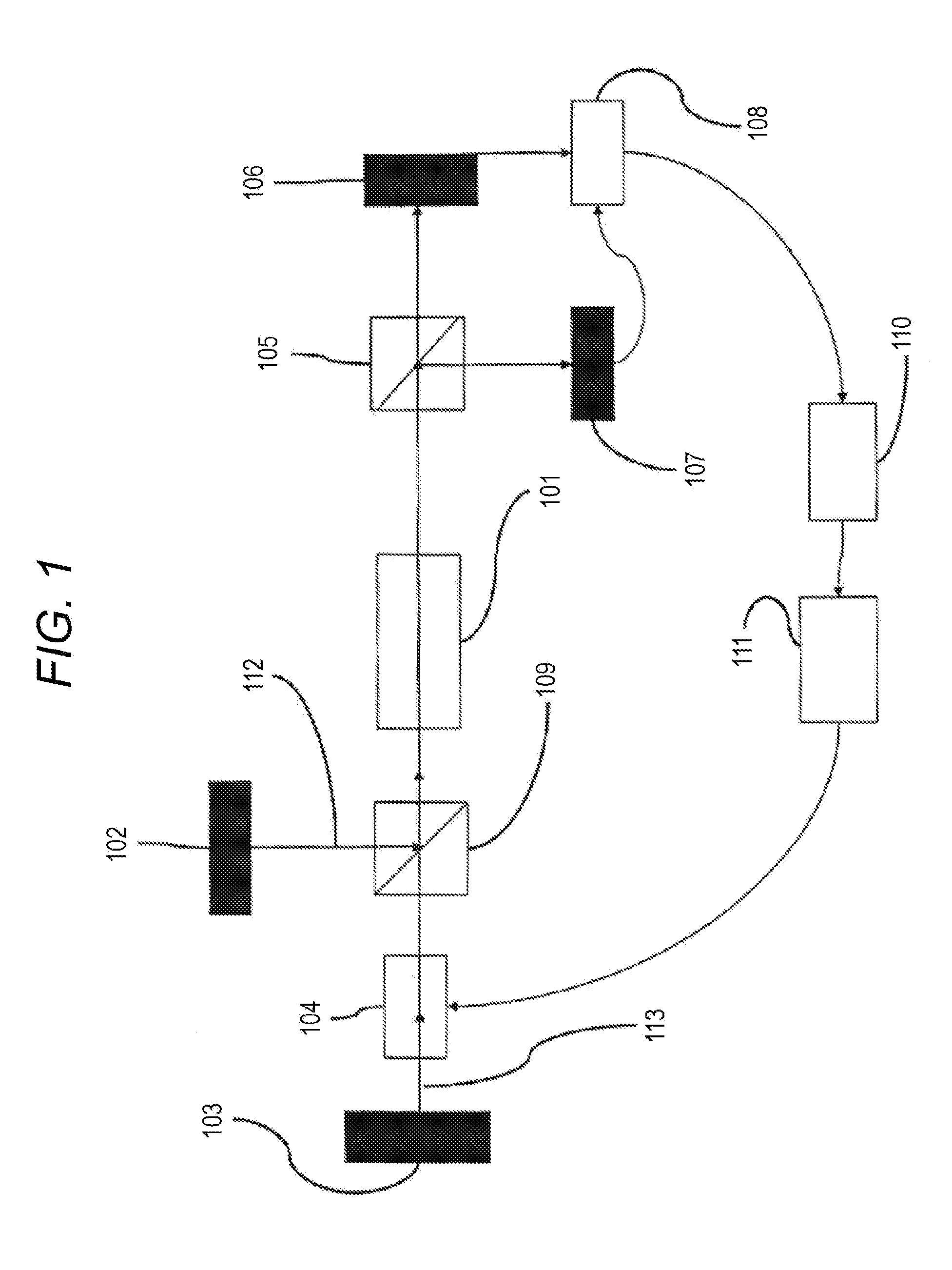
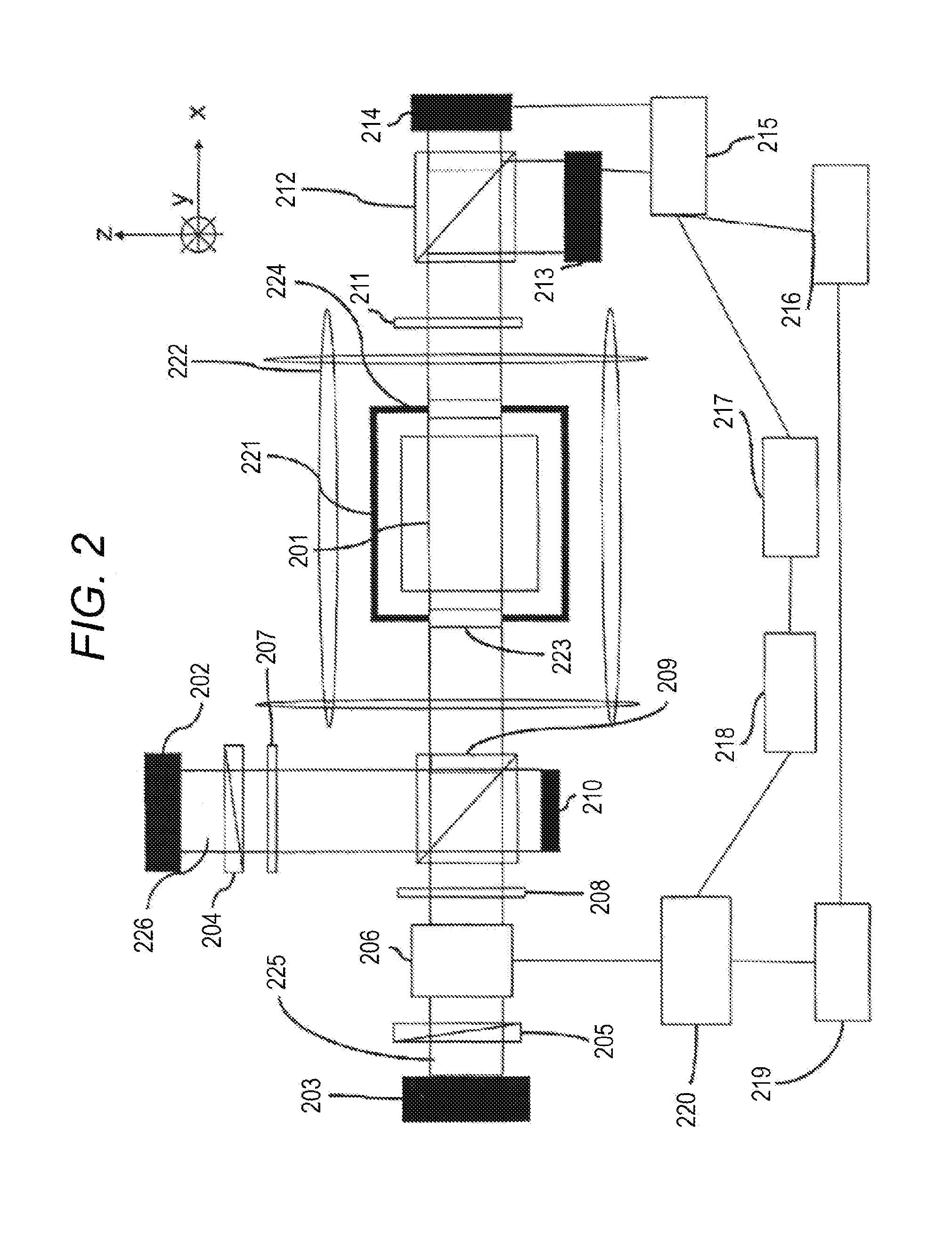
[0082]An exemplary configuration of an optically pumped magnetometer according to a first embodiment of the present invention is described with reference to FIG. 2.

[0083]As shown in FIG. 2, the optically pumped magnetometer of the present embodiment includes a cell 201 containing potassium (K), a pump light source 202, a probe light source 203, linear polarizers 204 and 205, an electrooptical phase modulation element 206, and ¼ wavelength plates 207 and 208.

[0084]Also, the optically pumped magnetometer includes a non-polarizing beam splitter 209, an optical terminator 210, a ½ wavelength plate 211, a polarization beam splitter element 212, photodetectors 213 and 214, a difference circuit 215, a lock-in amplifier 216, and a low-pass filter 217.

[0085]The optically pumped magnetometer further includes a polarization offset control circuit 218, an arbitrary waveform generator 219, a phase modulator power source 220, an isothermal heat-insulation bath 221, a three-axis Helmholtz coil 222...

second embodiment

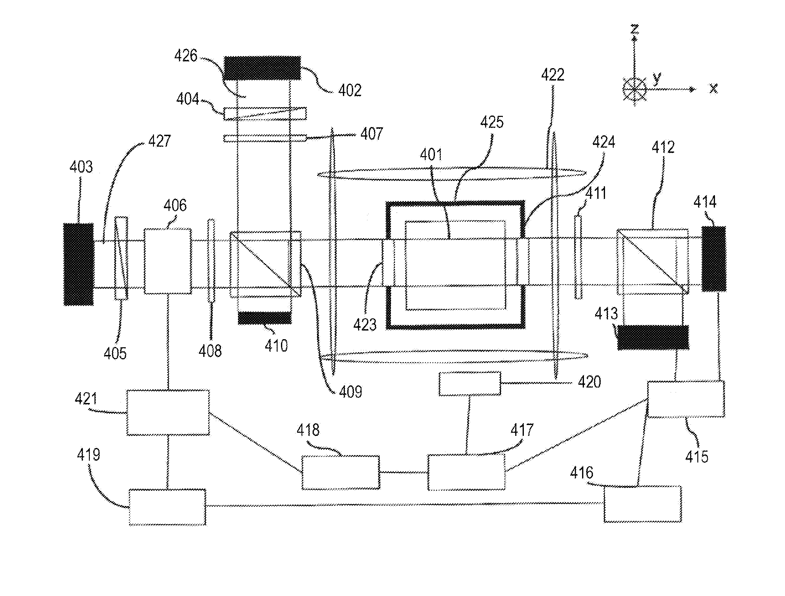
[0118]An exemplary configuration of an optically pumped magnetometer according to a second embodiment of the present invention is described with reference to FIG. 3.

[0119]As shown in FIG. 3, the optically pumped magnetometer of the present embodiment includes a cell 301 containing potassium (K), a pump light source 302, a probe light source 303, linear polarizers 304 and 305, an electrooptical phase modulation element 306, and ¼ wavelength plates 307 and 308.

[0120]Also, the optically pumped magnetometer includes a non-polarizing beam splitter 309, an optical terminator 310, a ½ wavelength plate 311, a polarization beam splitter element 312, photodetectors 313 and 314, a difference circuit 315, a lock-in amplifier 316, and a low-pass filter 317.

[0121]The optically pumped magnetometer further includes a polarization offset control circuit 318, an arbitrary waveform generator 319, a phase modulator power source 320, an isothermal heat-insulation bath 321, a three-axis Helmholtz coil 32...


PUM


Abstract

An optically pumped magnetometer having a single optical axis using atomic electron spin or nuclear spin includes a detection unit configured to detect an angle of a polarization plane of probe light having components of linear polarization and a modulation unit configured to apply a modulation to the angle of the polarization plane of the probe light having the components of linear polarization. The modulation unit is configured to control an offset in applying the modulation to the angle of the polarization plane of the probe light having the components of linear polarization according to the angle of the polarization plane of the probe light detected by the detection unit.

Description

BACKGROUND[0001]1. Technical Field[0002]The present disclosure relates to an optically pumped magnetometer and an optical pumping magnetic force measuring method, and specifically, to an optically pumped magnetometer using atomic electron spin or nuclear spin.[0003]2. Description of the Related Art[0004]There has been known an optically pumped magnetometer using atomic electron spin or nuclear spin.[0005]Cort Johnson, Peter D. D. Schwindt, and Michael Weisend, Appl. Phys. Lett. 97, 243703 (2010) (hereinafter referred to as Non-patent Literature 1) discloses an optically pumped magnetometer which includes a cell containing alkali metal gas, a pump light source, and a probe light source so as to detect a weak magnetic field.[0006]When an object magnetic field to be measured is applied to spin of an atom group, the spin of the atom group is polarized by the pump light rotates. This optically pumped magnetometer measures the above rotation as a rotation of a polarization plane of probe ...

Claims


Application Information

Patent Timeline
IPC IPC(8): G01R33/26
CPCG01R33/26
Inventor ICHIHARA, SUNAOKOBAYASHI, TETSUO
Owner CANON KK
Why Eureka
Try Eureka