Light guide assembly, backlight module and liquid crystal display

Active Publication Date: 2015-01-22
RADIANT OPTO ELECTRONICS
View PDF4 Cites 3 Cited by
  • Summary
  • Abstract
  • Description
  • Claims
  • Application Information

AI Technical Summary

Benefits of technology

[0008]One aspect of the present invention is to provide a light guide assembly, a backlight module and a LCD, in which a recess is disposed on an optical surface of a light guide plate to accommodate an adhes

Problems solved by technology

However, because the double faced adhesive tape 120 itself has a thickness, this securing method usin

Method used


Image

  • Light guide assembly, backlight module and liquid crystal display
  • Light guide assembly, backlight module and liquid crystal display
  • Light guide assembly, backlight module and liquid crystal display

Examples


Embodiment Construction

[0032]Reference will now be made in detail to the present embodiments of the invention, examples of which are illustrated in the accompanying drawings. Wherever possible, the same reference numbers are used in the drawings and the description to refer to the same or like parts.

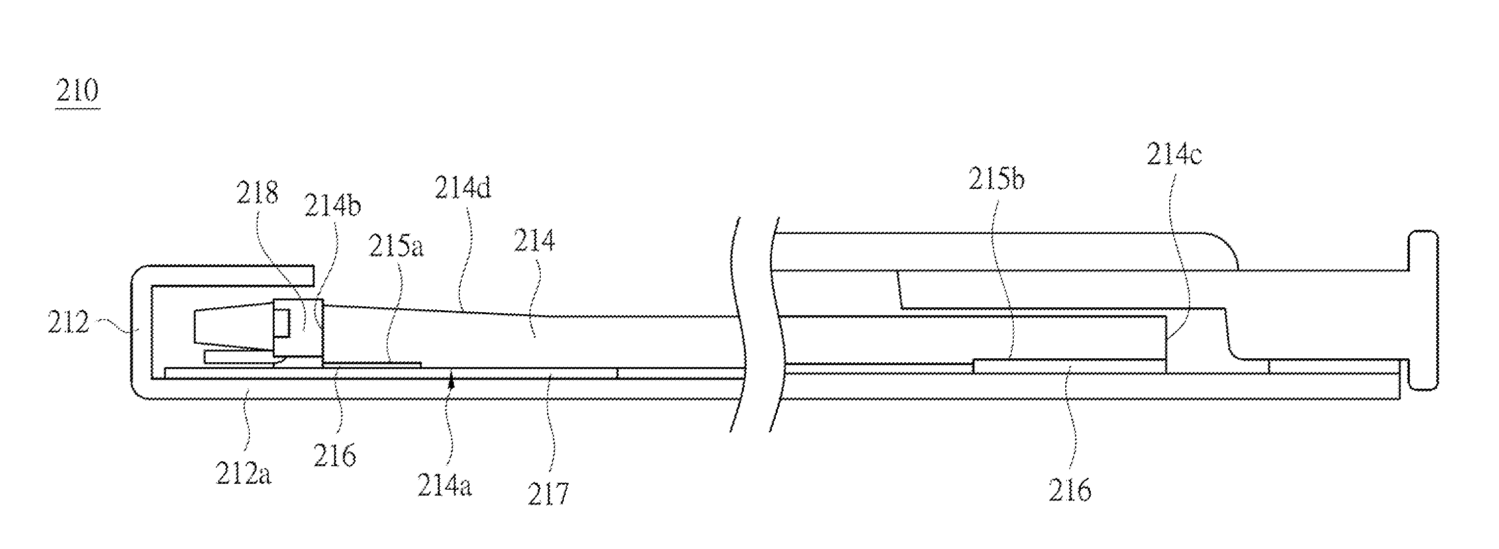
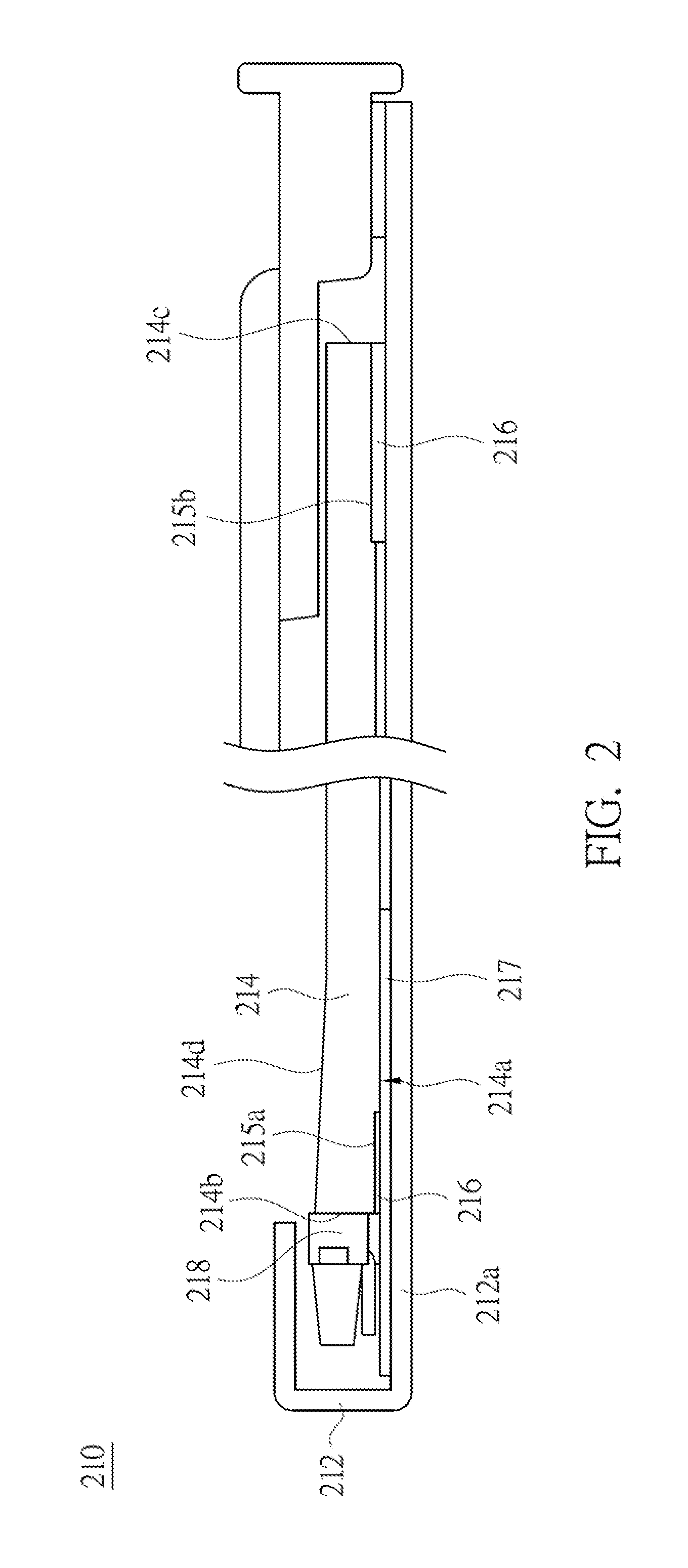
[0033]Referring to FIG. 2 and FIG. 3, FIG. 2 is a schematic cross-sectional view of a backlight module 210 according to an embodiment of the present invention, and FIG. 3 is a side view of a light guide plate of the backlight module 210 according to an embodiment of the present invention. In the present embodiment, the backlight module 210 mainly includes a back plate 212, a light guide plate 214, an adhesive member 216 and a light source 218.

[0034]As shown in FIG. 2, the back plate 212 has a holding surface212a. The light guide plate 214 is disposed on the holding surface 212a. The light guide plate 214 has a first optical surface 214a and a second optical surface 214d opposite to the first optical surface 21...


PUM


Abstract

A light guide assembly, a backlight module and a liquid crystal display (LCD) are provided. The backlight module includes a back plate light guide plate, an adhesive member and a light source. The light guide plate is disposed on the back plate and includes a first optical surface, a second optical surface and a light-incident surface. The first optical surface is opposite to the second optical surface. The light-incident surface connects the first optical surface and the second optical surface The first optical surface or the second optical surface of the light guide plate is set with recess. The adhesive member is disposed in the recess to adhere the light guide plate to the back plate. The light source is disposed on the back plate and emits light toward the light guide plate.

Description

RELATED APPLICATIONS[0001]This application claims priority to Taiwan Application Serial Number 102125600, filed Jul. 17, 2013, which is herein incorporated by reference.BACKGROUND[0002]1. Field of Invention[0003]The present invention relates to a light source module. More particularly, the present invention relates to a light guide assembly, a backlight module and a liquid crystal display.[0004]2. Description of Related Art[0005]A backlight module is one of the critical components of a liquid crystal display (LCD). Currently, liquid crystal displays (LCDs) have been widely used in portable electronic products with high-growth potentials such as cell phones, notebook computers, digital cameras, etc. With the trend of portable electronic products toward thinness and lightweight, how to reduce the thickness of the backlight module is an object to which people in the related industries are devoted.[0006]Referring to FIG. 1, FIG. 1 is a schematic cross-sectional view of a conventional ba...

Claims


Application Information

Patent Timeline
IPC IPC(8): F21V8/00
CPCG02B6/0013G02B6/0088G02B6/002G02B6/0055G02F1/133524G02F2202/28G02F1/133512
Inventor HSU, YU-HUNGCHEN, JUI-LIN
Owner RADIANT OPTO ELECTRONICS
Why Eureka
Try Eureka