Switching power supply device

Active Publication Date: 2015-01-22
MITSUMI ELECTRIC CO LTD
View PDF6 Cites 37 Cited by
  • Summary
  • Abstract
  • Description
  • Claims
  • Application Information

AI Technical Summary

Benefits of technology

The invention is a power supply device that has a transformer with low loss and high power efficiency. It is compact and cost-effective, without causing any troubles due to reverse current.

Problems solved by technology

Unfortunately, this installation increases the number of components, which leads to increases in size and costs of the device.

Method used


Image

  • Switching power supply device
  • Switching power supply device
  • Switching power supply device

Examples


Embodiment Construction

[0036]A preferred embodiment of the invention will now be described with reference to the drawings.

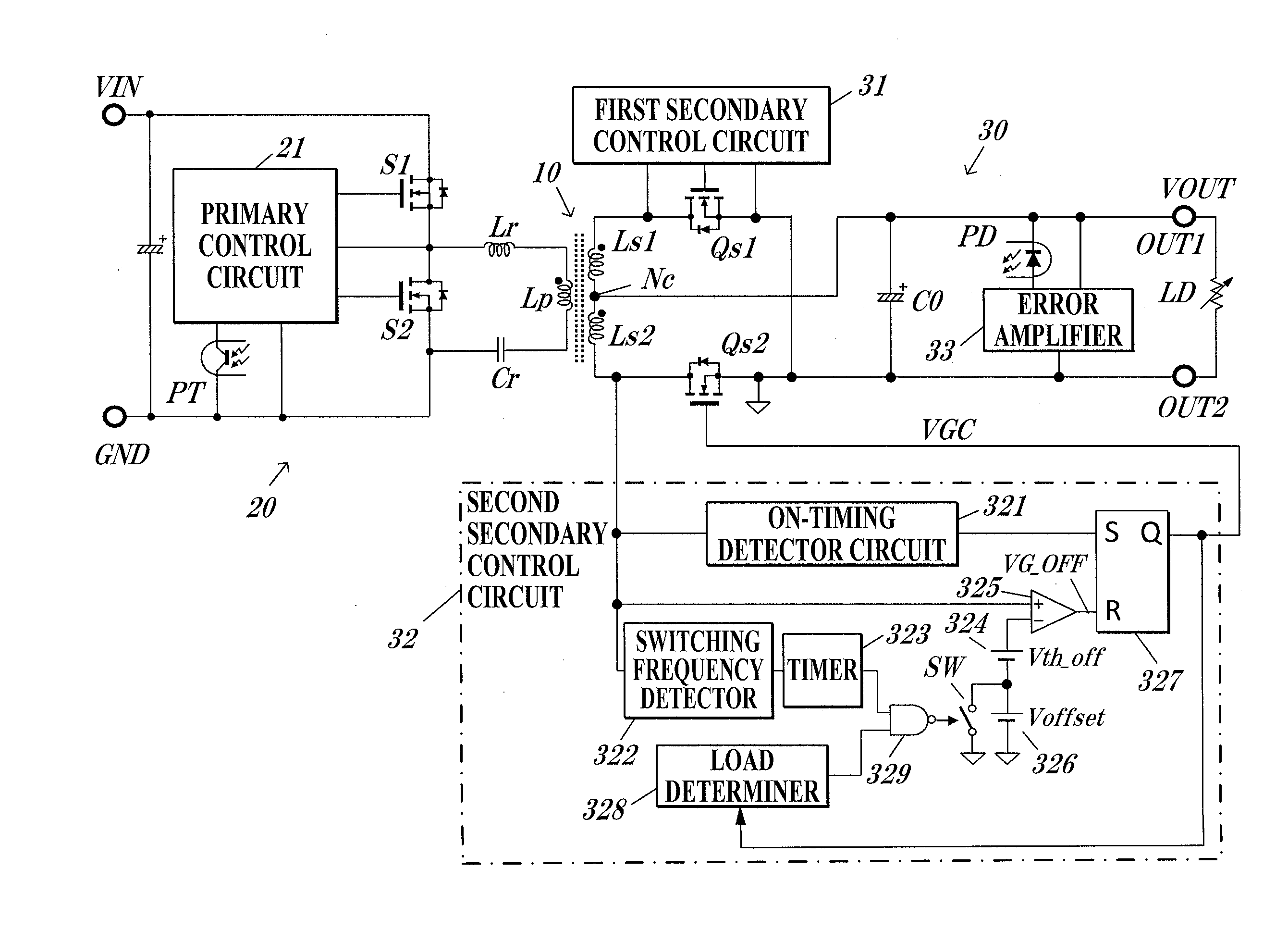
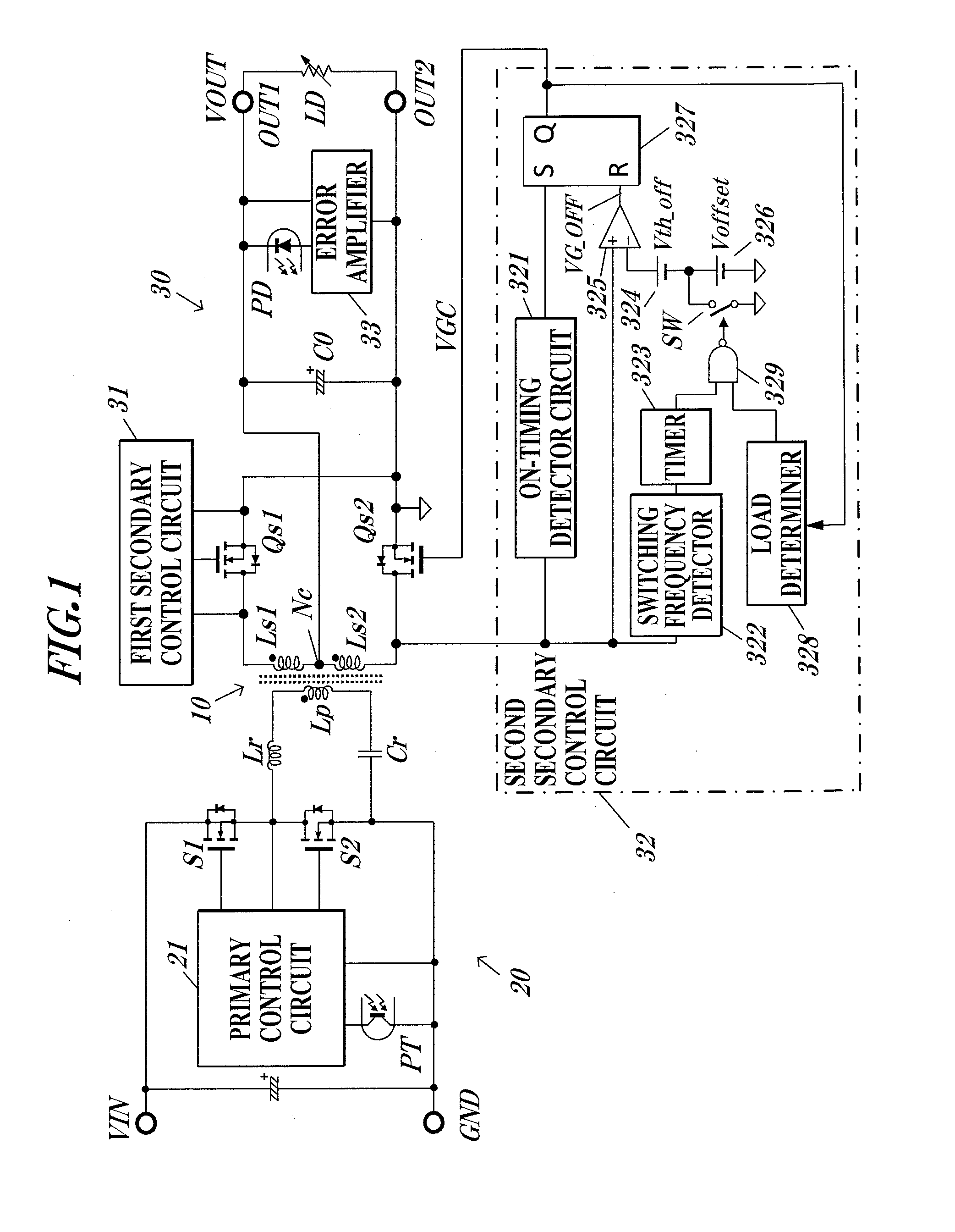
[0037]FIG. 1 illustrates a current-resonant switching power supply device according to an embodiment of the invention.

[0038]The current-resonant switching power supply device according to the embodiment includes a power converting transformer 10, a half-bridge series resonant circuit 20 on the primary winding of the transformer 10, and a full-wave rectifier circuit 30 including synchronous rectifying switches on the secondary winding of the transformer 10.

[0039]The primary series resonant circuit 20 includes a resonant inductor Lr and a resonant capacitor Cr connected in series to a primary coil Lp of the transformer 10. The series resonant circuit 20 further includes main switching elements S1 and S2 consisting of n-channel MOS transistors that are connected in series between a voltage input terminal VIN and a terminal GND. A DC voltage from a DC voltage source (including a diode brid...


PUM


Abstract

In a switching power supply device having low loss in synchronous rectifying switches, exhibiting high power efficiency, and not causing troubles by reverse current in the switches. A secondary control circuit includes a reference voltage circuit to generate a reference voltage having a predetermined potential, and an ON-timing detector circuit to detect an ON timing of a synchronous rectifying switch through monitoring of a terminal voltage of the switch, an OFF-timing detector circuit to detect an OFF timing of the switch, and a timer circuit to be turned on at the ON timing and measure a predetermined period. The threshold voltage consisting of the reference voltage generated by the reference voltage circuit and an offset voltage is applied to the OFF-timing detector circuit during the measurement of the timer circuit, and the threshold voltage consisting of the reference voltage is applied to the OFF-timing detector circuit during the non-measurement.

Description

TECHNICAL FIELD[0001]The present invention relates to a switching type power supply device including a transformer for power conversion, for example, an advantageous technique for a current-resonant switching power supply device including a series resonant circuit on the primary winding of a transformer and synchronous rectifying switches on the secondary winding of the transformer.BACKGROUND ART[0002]One of the conventional switching power supply devices is a current resonant converter including a series resonant circuit on the primary winding of a transformer. The current resonant converter includes the series resonant circuit including a resonant inductor and a resonant capacitor connected in series to a primary coil of the transformer, and a pair of switching elements to control current flowing from a DC-voltage input terminal to the series resonant circuit. The switching elements are alternately turned on or off at a frequency near the resonance frequency such that sinusoidal c...

Claims


Application Information

Patent Timeline
IPC IPC(8): H02M3/335H02M1/00
CPCH02M3/33592H02M2001/0054Y02B70/1475Y02B70/1491Y02B70/10H02M1/0054H02M3/33571H02M3/01H02M3/33576H02M1/0025H02M7/4815H02M7/4818
Inventor HYUGAJI, TAKUMIENDO, NAOTO
Owner MITSUMI ELECTRIC CO LTD
Why Eureka
Try Eureka