Cylindrical graphene nanoribbon on metal

a graphene nanoribbon and cylindrical technology, applied in the field of graphene nanoribbon fabrication, can solve the problems of cracks, cracks, and other discontinuities that may readily occur, and achieve the effect of preventing cracks and other discontinuities

Inactive Publication Date: 2015-01-22
LOCKHEED MARTIN CORP
View PDF0 Cites 3 Cited by
  • Summary
  • Abstract
  • Description
  • Claims
  • Application Information

AI Technical Summary

Benefits of technology

[0003]Accordingly, 3D graphene nanoribbons and methods for fabricating 3D graphene nanoribbons that may readily be utilized in a variety of devices including, for example as solenoid windings and the like, are provided.

Problems solved by technology
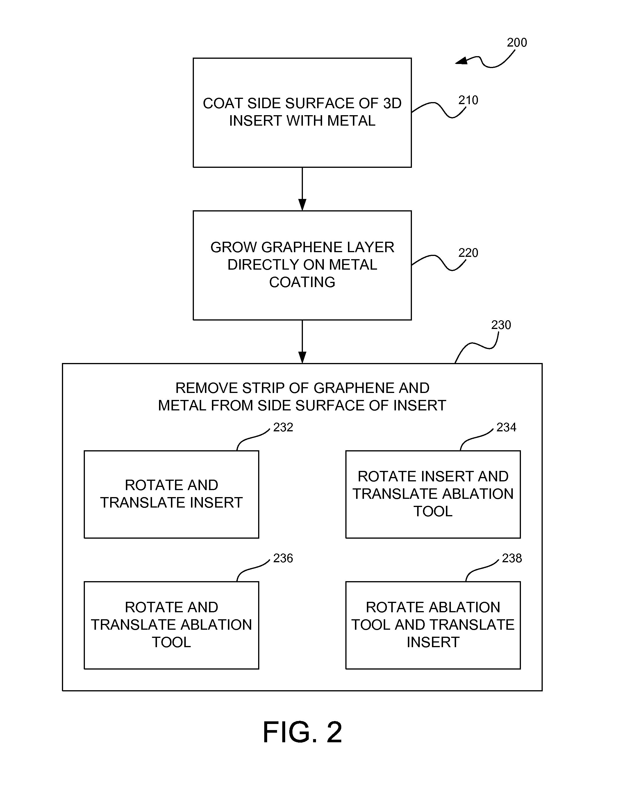
However, in order to use long GNRs as solenoid windings or in other generally 3D applications, challenging lift-off techniques must be undertaken in order to remove 2D fabricated GNRs from the surfaces on which they are formed.
Given their ultra-thin nature, breaks, cracks, or other discontinuities may readily occur during such lift-off processes.

Method used


Image

  • Cylindrical graphene nanoribbon on metal
  • Cylindrical graphene nanoribbon on metal
  • Cylindrical graphene nanoribbon on metal

Examples


Embodiment Construction

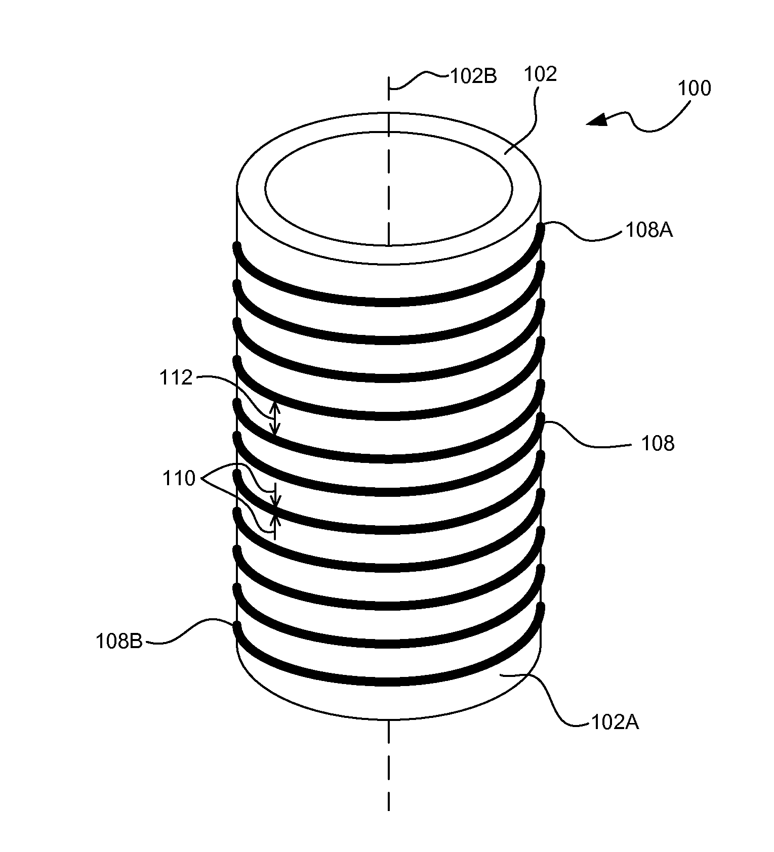
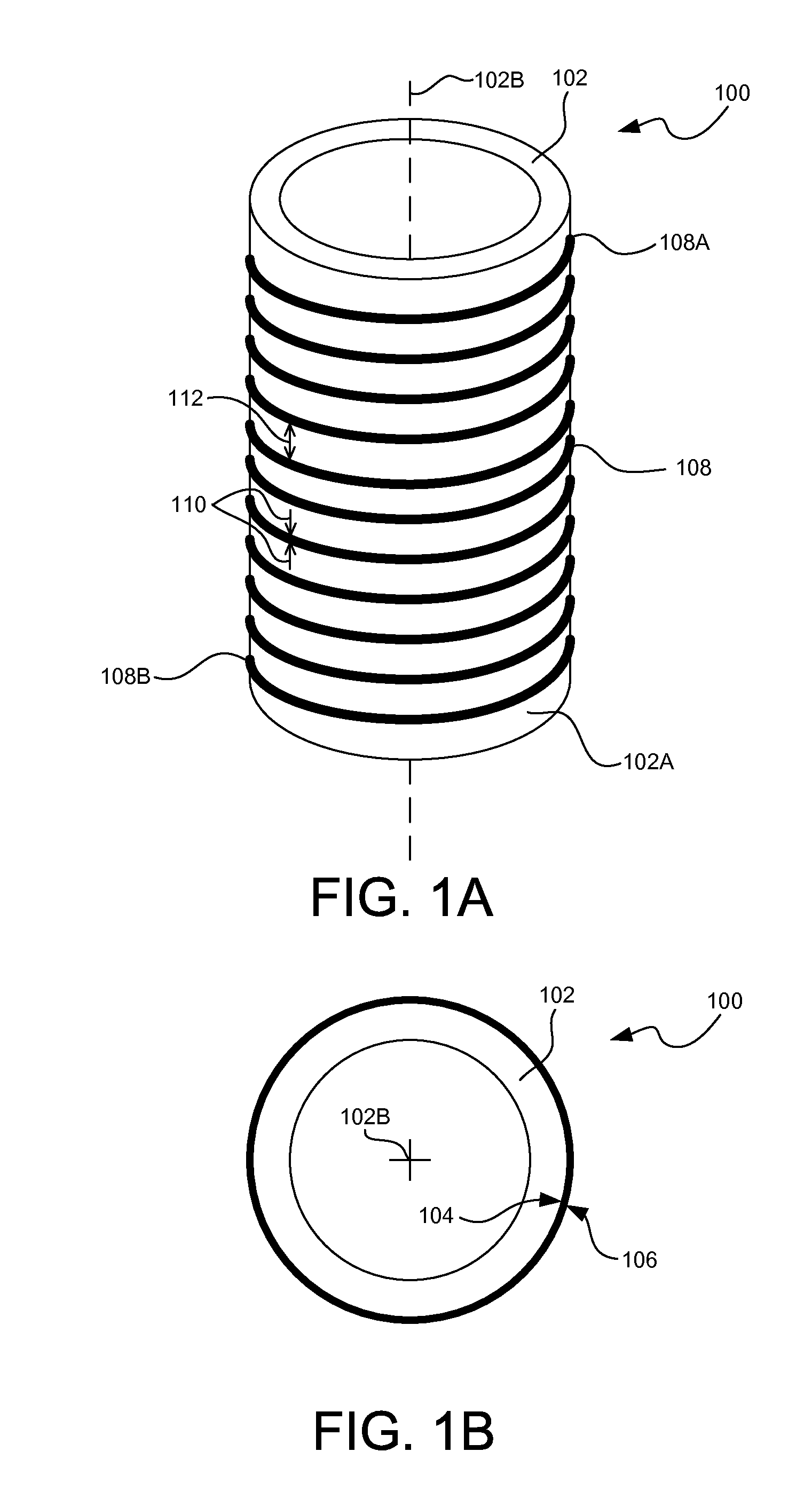
[0011]FIGS. 1A-1B show side perspective and end views of one embodiment of a three-dimensional (3D) graphene nanoribbon 100. The 3D graphene nanoribbon 100 is formed on the side surface 102A of an insert 102 having a circular or elliptical cross-section and a longitudinal axis 102B. In this regard, the insert 102 may, for example, be a cylinder, a cone or the like. In other embodiments, it may be possible for the insert 102 to have differently a shaped cross-section such as, for example, triangular, rectangular, pentagonal, hexagonal, etc. The insert 102 may be comprised of a ceramic material (e.g., silicon). The insert 102 may be appropriately sized (e.g., in height and diameter), in order to accommodate formation of a sufficient number of windings thereon for the intended application of the 3D graphene nanoribbon 100. As depicted in FIGS. 1A-1B, the insert 102 may be hollow. In other embodiments, the insert 102 may be solid.

[0012]The side surface 102A of the insert 102 has a metal...


PUM

PropertyMeasurementUnit
widthaaaaaaaaaa
widthaaaaaaaaaa
crystal lattice structureaaaaaaaaaa

Abstract

Three-dimensional (3D) graphene nanoribbons and methods for fabricating 3D graphene nanoribbons that may readily function as solenoid windings and the like. In one embodiment, a method of fabricating a 3D graphene nanoribbon (100) may include coating a side surface (102A) of a 3D insert (102) with a metal (104) appropriate for graphene growth thereon. The method may also include growing a layer (106) of graphene directly on the metal coating. The method may also include removing a strip of the graphene layer and metal coating (106/104) to expose the side surface (102A) of the insert (102) while leaving a line (108) of graphene on metal winding around the insert (102) and extending continuously from a first end (108A) of the line (108) to a second end (108B) of the line (108).

Description

FIELD OF THE INVENTION[0001]The present invention relates generally to the fabrication of graphene nanoribbons (GNRs), and more particularly to three-dimensional (3D) GNRs and their fabrication.BACKGROUND OF THE INVENTION[0002]Graphene is generally understood to be a pure carbon substance that is an allotrope of carbon whose structure is a single planar sheet of sp2-bonded carbon atoms densely packed in a honeycomb crystal lattice structure. GNRs are ultra-thin lines of graphene. Since graphene exhibits properties such as high carrier mobility, GNRs have been considered for use in high-performance electronic devices such as, for example, as conductors for solenoid windings. Two-dimensional (2D) fabrication techniques where long GNRs are fabricated on flat surfaces are possible. However, in order to use long GNRs as solenoid windings or in other generally 3D applications, challenging lift-off techniques must be undertaken in order to remove 2D fabricated GNRs from the surfaces on whi...

Claims


Application Information

Patent Timeline
Patent Type & Authority Applications(United States)
IPC IPC(8): C23C14/18B23K26/36C01B31/04
CPCC01B31/0446C23C14/18B23K26/365B23K26/0823C01B31/0453C01B2204/06C23C14/0005C23C14/0605C30B23/025C30B29/02C30B29/60C01B32/186B23K26/361Y10T428/292
Inventor WILLIAMS, DANIELLESCHWARTZ, REBECCA
Owner LOCKHEED MARTIN CORP
Why Eureka
Try Eureka