
Bi-directional fixating/locking transvertebral body screw/intervertebral cage stand-alone constructs having a central screw locking lever, and pliers and devices for spinal fusion

Active Publication Date: 2015-01-22
MOSKOWITZ FAMILY LLC
View PDF7 Cites 40 Cited by
  • Summary
  • Abstract
  • Description
  • Claims
  • Application Information

AI Technical Summary

Benefits of technology

The present invention is a new bi-directional fixating transvertebral (BDFT) screw / cage apparatus that solves the problems of conventional apparatus by improving upon their designs. It combines the functions of an intervertebral cage spacer and a fixating screw, and can be used for posterior and anterior lumbar and cervical placements. The apparatus facilitates a flexible fusion and avoids the complications associated with traditional pedicle screw placement, such as potential nerve and vascular injury, violation of healthy facets, and overly rigid fusions. It also recognizes the advantage of transpedicular screws in creating a strong solid fusion, while avoiding inflexibility of all columns which leads to increasing segmental stress and a higher rate of re-operation.

Problems solved by technology

Complications of pedicle screw placement in cervical, thoracic and lumbosacral spine include duration of procedure, significant tissue dissection and muscle retraction, misplaced screws with neural and / or vascular injury, excessive blood loss, need for transfusions, prolonged recovery, incomplete return to work, and excessive rigidity leading to adjacent segmental disease requiring further fusions and re-operations.

Method used


Image

  • Bi-directional fixating/locking transvertebral body screw/intervertebral cage stand-alone constructs having a central screw locking lever, and pliers and devices for spinal fusion
  • Bi-directional fixating/locking transvertebral body screw/intervertebral cage stand-alone constructs having a central screw locking lever, and pliers and devices for spinal fusion
  • Bi-directional fixating/locking transvertebral body screw/intervertebral cage stand-alone constructs having a central screw locking lever, and pliers and devices for spinal fusion

Examples


Embodiment Construction

[0038]Aspects of the invention are disclosed in the following description and related drawings directed to specific embodiments of the invention. Alternate embodiments may be devised without departing from the scope of the invention. Additionally, well-known elements of the invention will not be described in detail or will be omitted so as not to obscure the relevant details of the invention.

[0039]The word “exemplary” is used herein to mean “serving as an example, instance, or illustration.” Any embodiment described herein as “exemplary” is not necessarily to be construed as preferred or advantageous over other embodiments. Likewise, the term “embodiments of the invention” does not require that all embodiments of the invention include the discussed feature, advantage or mode of operation.

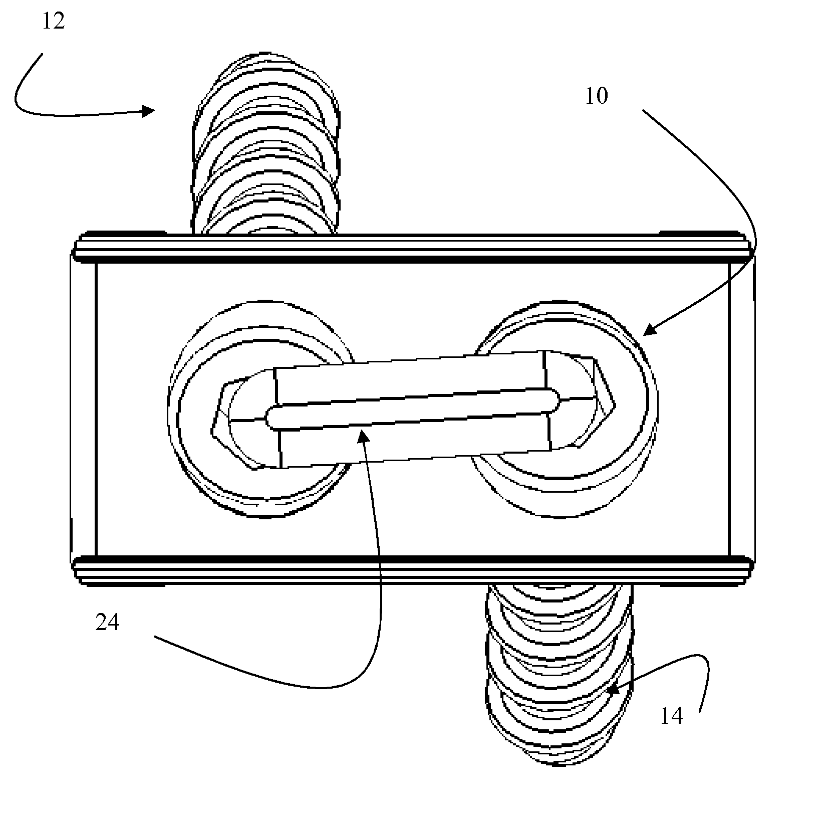
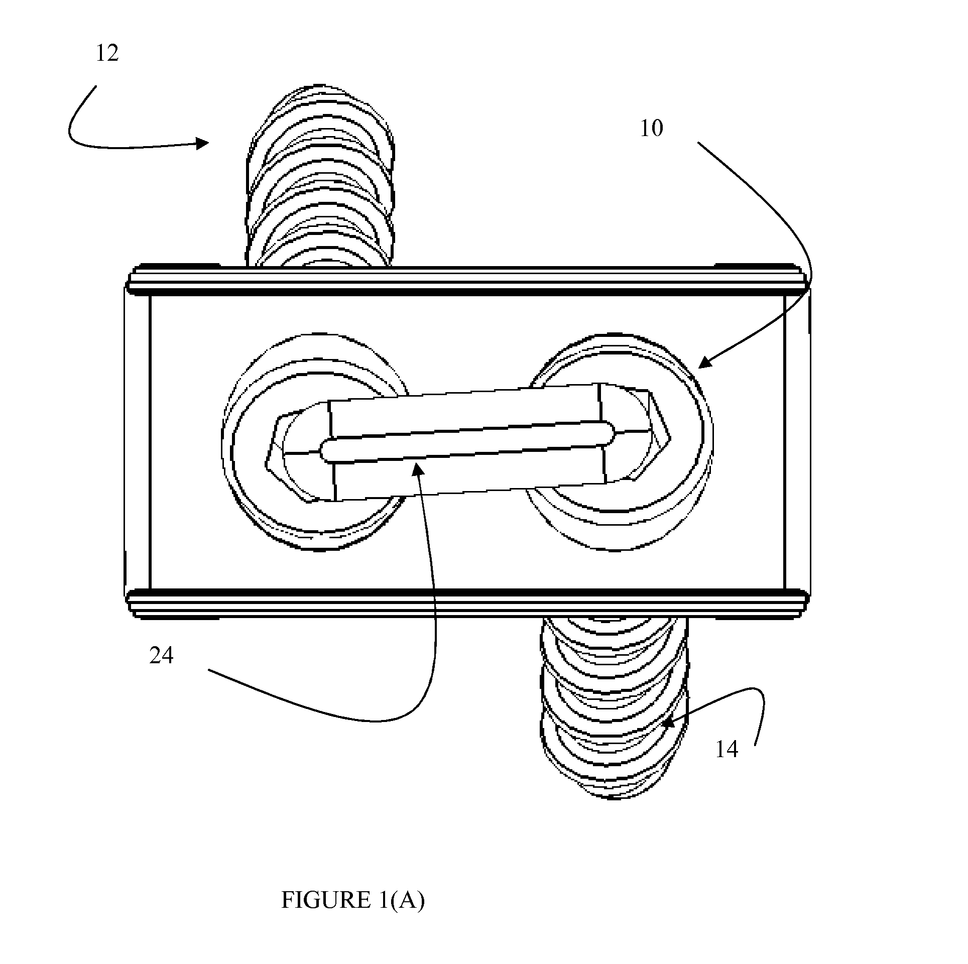
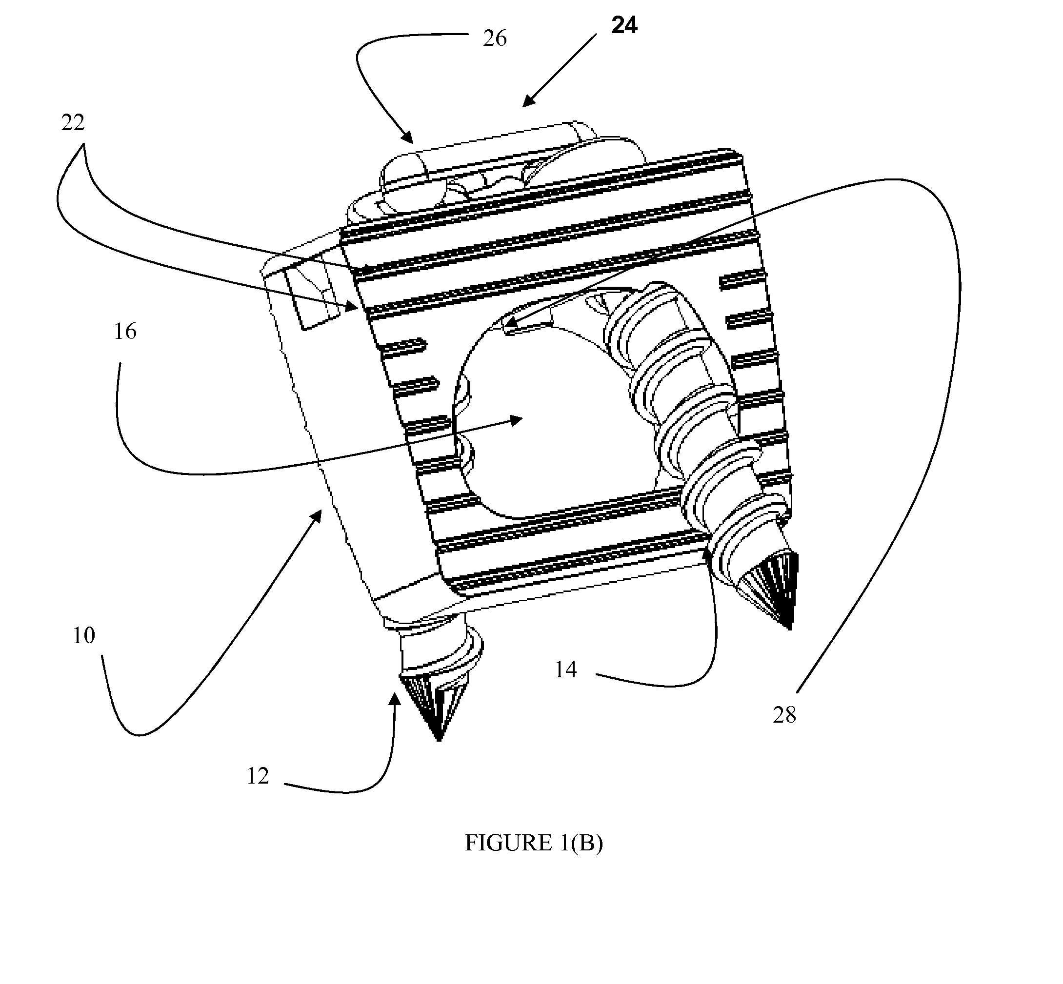
[0040]With reference to FIGS. 1A-10C, exemplary embodiments of the invention will now be described.

[0041]1. The Medical Device

[0042]Referring to FIGS. 1-5, the above described problems of the conven...


PUM


Abstract

A bi-directional fixating transvertebral (BDFT) screw / cage apparatus including an intervertebral cage for maintaining disc height, and a method of inserting the same is provided. The intervertebral cage includes a first internal screw guide and a second internal screw guide, a first screw member and a second screw member, and a central screw locking lever coupled to the intervertebral cage, wherein the central screw locking lever prevents the first screw member and the second screw from pulling-out of the first internal screw guide and the second internal screw guide. The central screw locking lever includes a rotatable handle and stem portion, or a screw locking horizontal bracket. A pliers device for inserting and removing the bi-directional fixating transvertebral (BDFT) screw / cage apparatus, a posterior cervical and lumbar facet joint staple, and a staple gun for a posterior cervical and lumbar facet joint staple also are provided.

Description

[0001]This application is a Divisional Application of Ser. No. 12 / 471,340 filed May 22, 2009, which is a Continuation-In-Part Application of application Ser. No. 12 / 054,335 filed on Mar. 24, 2008, now U.S. Pat. No. 7,972,363 issued Jul. 5, 2011, which is a Continuation-In-Part of application Ser. No. 11 / 842,855, filed on Aug. 21, 2007, now U.S. Pat. No. 7,942,903 issued May 17, 2011, which is a Continuation-In-Part of application Ser. No. 11 / 536,815, filed on Sep. 29, 2006, now U.S. Pat. No. 7,846,188 issued Dec. 7, 2010, which is a Continuation-In-Part of application Ser. No. 11 / 208,644, filed on Aug. 23, 2005, now U.S. Pat. No. 7,704,279 issued Apr. 27, 2010, and this application also claims priority under 35 U.S.C. §119(e) of U.S. Provisional Application No. 60 / 670,231, filed on Apr. 12, 2005; the entire contents of all of the above identified patent applications are hereby incorporated by reference in their entirety.[0002]This application is related to applicants' U.S. Pat. No. ...

Claims


Application Information

Patent Timeline
IPC IPC(8): A61F2/44A61B17/70
CPCA61F2/442A61F2220/0041A61B17/7074A61B17/86A61F2002/30331A61B2017/0641A61F2/447A61F2220/0025A61F2002/448A61F2002/30772A61F2002/30476A61B2017/0648A61B2017/922A61F2002/2835A61F2002/30787A61B17/8042A61F2002/4641A61B17/068A61F2002/4622A61F2002/30879A61B17/7064A61F2220/0033A61B17/809A61B17/0642A61F2002/305A61F2002/30383A61F2002/30604A61B2017/0647A61F2/4637A61F2002/30517
Inventor MOSKOWITZ, AHMNON D.MOSKOWITZ, NATHAN C.MOSKOWITZ, MOSHEH T.ALVARADO, PABLO A. VALDIVIA Y.
Owner MOSKOWITZ FAMILY LLC
Features
  • Generate Ideas
  • Intellectual Property
  • Life Sciences
  • Materials
  • Tech Scout
  • Unparalleled Data Quality
  • Higher Quality Content
  • 60% Fewer Hallucinations
Learn More