Method for operating a brake system for motor vehicles, and brake system

a brake system and motor vehicle technology, applied in the direction of braking systems, instruments, analogue processes for specific applications, etc., can solve the problems of impact noise inside the multiplex valve, and achieve the effect of significantly reducing the impact noise of the inlet valve and little for

Active Publication Date: 2015-01-22
CONTINENTAL TEVES AG & CO OHG
View PDF7 Cites 30 Cited by
  • Summary
  • Abstract
  • Description
  • Claims
  • Application Information

AI Technical Summary

Benefits of technology

[0008]An advantage of the invention is that the impact noises of the inlet valves are significantly reduced, since the inlet valves are continuously closed and are only overflowed during the pressure build-up. There is no impact against the rear stop as the inlet valves are opened, and the overflowed inlet valves close slowly and with little force as the pressure build-up ends.
[0009]The inlet valves are analogized or analog-controlled inlet valves which in each case are activated by an electrical activation quantity. The inlet valves are preferably actuated by means of an activation current. In the unactivated state the inlet valves are open (for example, are of currentlessly open configuration). Thus, by appropriate selection of the value of the activation quantity, it can be predetermined whether or at which pressure of the pressure supply device a closed inlet valve can, or cannot, be overflowed by means of the pressure supply device. More precisely, the force acting on the valve piston, which force itself defines the overflow pressure required to open the inlet valve, is determined by the value (magnitude) of the electrical activation quantity supplied to the inlet valve.
[0010]For an activation of the inlet valves as accurate as possible, an activation characteristic, which describes a dependence of the electrical activation quantity on a differential pressure or pressure acting on the inlet valve, is preferably predetermined for each inlet valve. The activation characteristics may be determined at the factory and stored in an electronic control and regulation unit, for example of the brake system. Especially preferably, the activation characteristics of the individual inlet valves are measured by means of the pressure supply device during operation of the vehicle and stored in the electronic control and regulation unit so as to be available for pressure regulation.
[0011]The brake system preferably includes one outlet valve per wheel brake. By means of the outlet valves, requirements for pressure reduction in one or more wheel brakes can be met independently of one another and simultaneously with a pressure build-up in another wheel. The outlet valves advantageously connect the wheel brakes to a pressure medium reservoir. Especially preferably, the outlet valves are configured to be currentlessly closed, that is, are in a blocked state in the unactivated state.
[0012]The pressure medium volume to be displaced into the predefined group by the pressure supply device in order to build up pressure to a predetermined pressure value is preferably determined with reference to the pressure-volume relationship or relationships and to the reference pressure or pressures of the one or more wheel brakes of the predefined group. Especially preferably, the pressure medium volume to be displaced is equal to the wheel take-up volume of the single wheel brake of the predefined group or to the sum of the wheel take-up volumes of the plurality of wheel brakes of the predefined group. Each wheel take-up volume is determined, with reference to the predetermined pressure value, from the pressure-volume relationship of the corresponding wheel brake.
[0013]According to a development of the invention, the displacement of the pressure medium volume is effected by a volume control or position control (travel control) of the pressure supply device. The control is advantageously carried out while taking account of the pressure-volume relationship(s) and of the reference pressure(s) of the one or more wheel brakes of the predefined group.

Problems solved by technology

Here, the not inconsiderable noise generation is considered disadvantageous, which noise results inter alia from the fact that, firstly, the electric motor has to execute high-frequency reversing operations of the piston-cylinder system and, secondly, the multiplex valves have to be closed and opened in rapid succession, causing impact noises inside the multiplex valves.

Method used


Image

  • Method for operating a brake system for motor vehicles, and brake system
  • Method for operating a brake system for motor vehicles, and brake system
  • Method for operating a brake system for motor vehicles, and brake system

Examples


Embodiment Construction

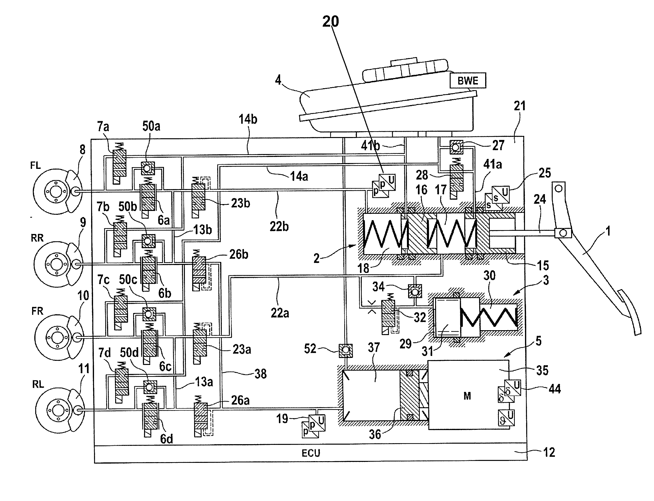
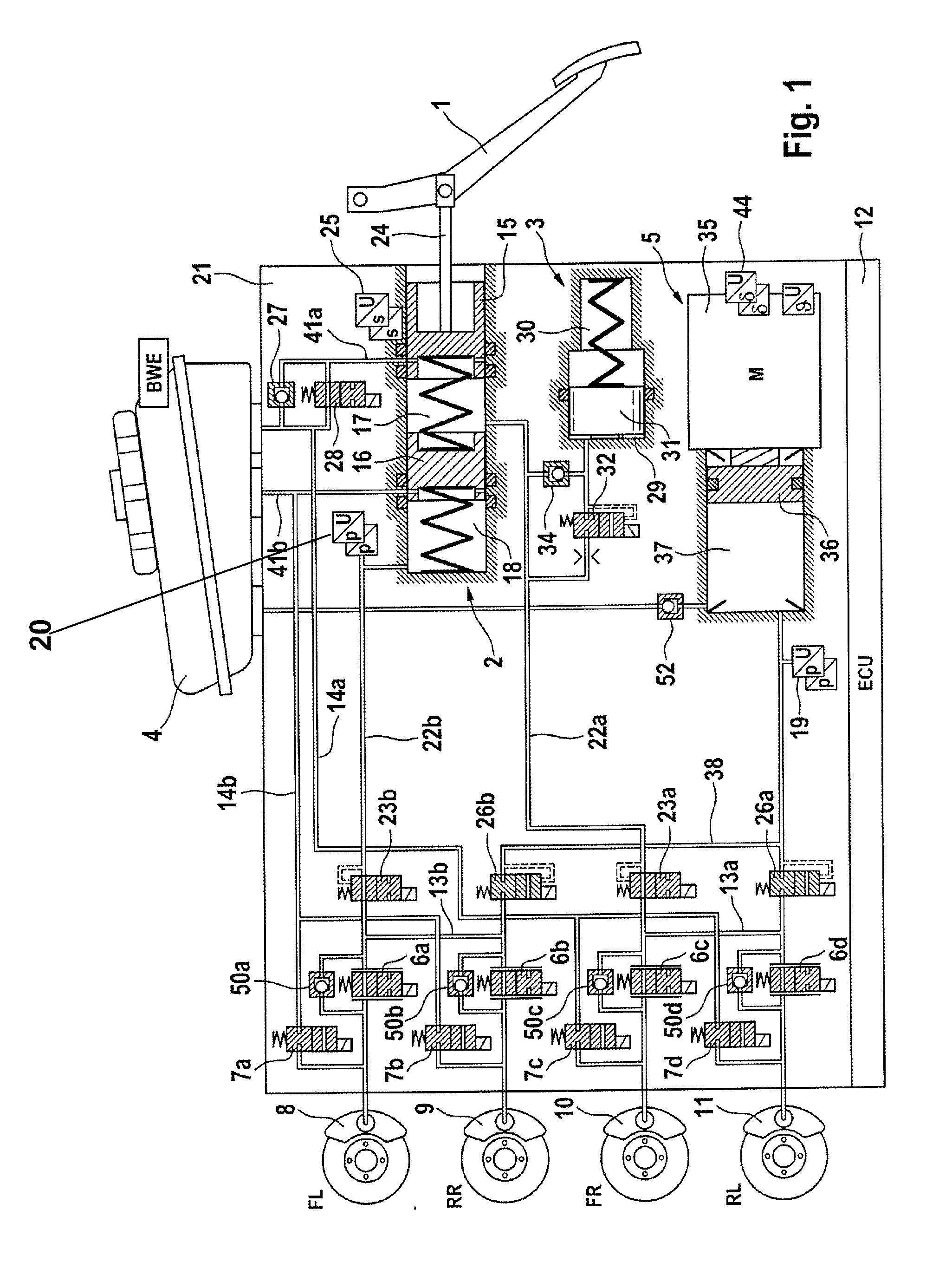
[0034]FIG. 1 shows an exemplary brake system for carrying out a method according to the invention in a schematic representation. The brake system comprises essentially a hydraulic actuating unit 2 which can be actuated by means of an actuating or brake pedal 1, a travel simulator or simulation device 3 cooperating with the hydraulic actuating unit 2, a pressure medium reservoir 4 under atmospheric pressure and associated with the hydraulic actuating unit 2, an electrically controllable pressure supply device 5, an electronic control and regulation unit 12 and an electrically controllable pressure modulation arrangement.

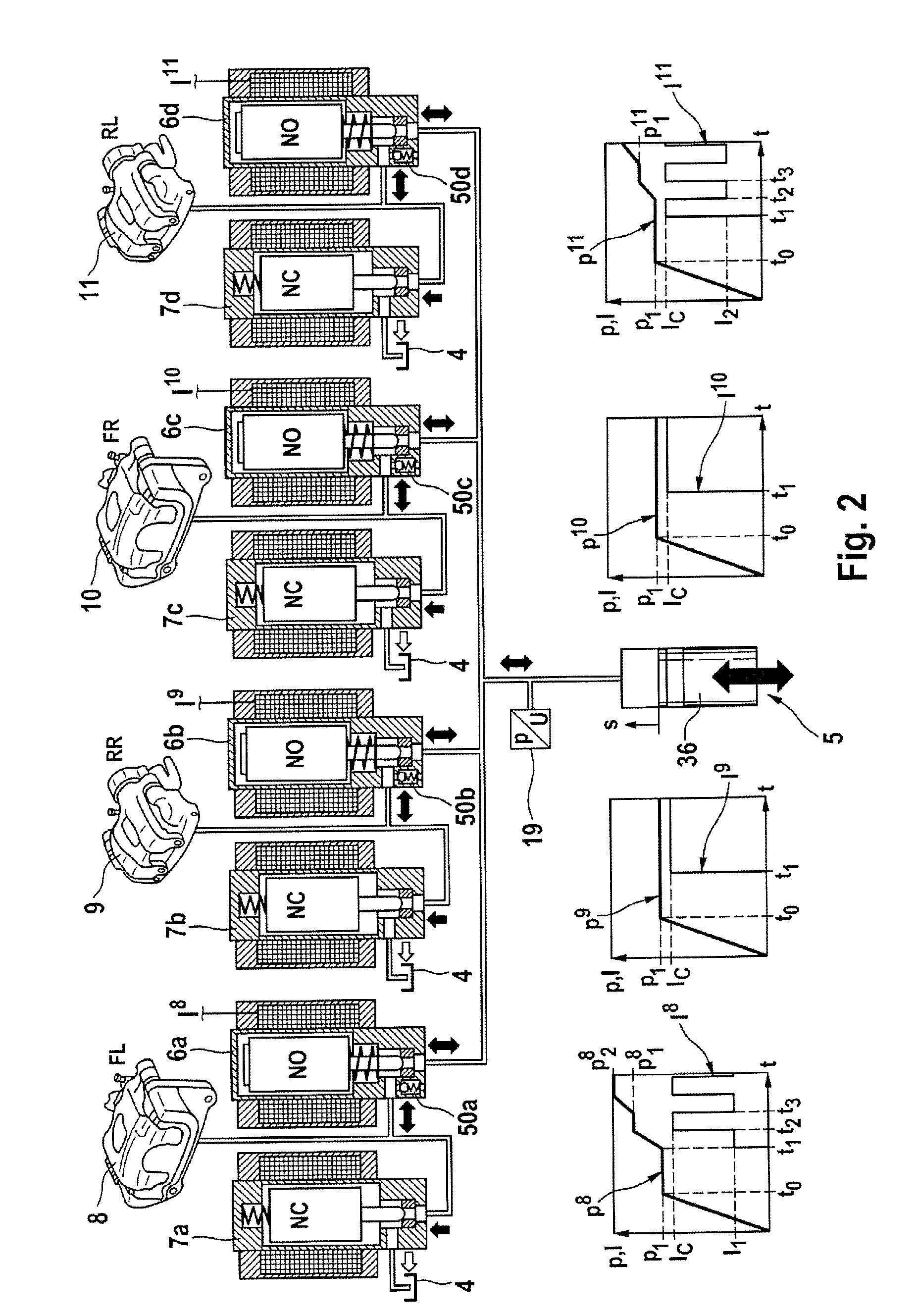
[0035]In the example, the pressure modulation arrangement comprises, for each wheel brake 8, 9, 10, 11 of a motor vehicle (not shown), an inlet valve 6a-6d and an outlet valve 7a-7d which are coupled hydraulically in pairs via central connections and are connected to the wheel brakes 8, 9, 10, 11. The inlet ports of the inlet valves 6a-6d are supplied, by means of bra...


PUM


Abstract

A method and system for operating a motor vehicle brake system, including several wheel brakes, an electrically controllable pressure supply device, dispenses a pressure medium volume for actuating the brakes, and an analogized or analog-controlled inlet valve, arranged in each wheel brake between the pressure supply device and wheel brake, for adjusting wheel-individual brake pressures. A check valve is connected in parallel to each inlet valve. At the start of a wheel-individual brake pressure control, all inlet valves are closed, and a pressure build-up is carried out in a predetermined group of one or more wheel brakes by displacing a pressure medium volume into the predetermined group of wheel brakes by the pressure supply device. Each inlet valve of the predetermined group is controlled such that the inlet valve is overflowed, wherein each inlet valve of the remaining wheel brakes is controlled such that the inlet valve remains closed.

Description

CROSS REFERENCE TO RELATED APPLICATIONS[0001]This application is the U.S. National Phase Application of PCT International Application No. PCT / EP2013 / 054354, filed Mar. 5, 2013, which claims priority to German Patent Application No. 10 2012 203 492.7, filed Mar. 6, 2012 and German Patent Application No. 10 2013 203 594.2, filed Mar. 4, 2013, the contents of such applications being incorporated by reference herein.FIELD OF THE INVENTION[0002]The invention relates to a method for operating a brake system and to a brake system.BACKGROUND OF THE INVENTION[0003]In automotive technology “brake-by-wire” brake systems are being used increasingly widely. Such brake systems often include, in addition to a brake master cylinder which can be actuated by the vehicle driver, an electrically controllable pressure supply device by means of which actuation of the wheel brakes or of the brake master cylinder takes place in the brake-by-wire operating mode. In order to communicate an agreeable pedal fe...

Claims


Application Information

Patent Timeline
Patent Type & Authority Applications(United States)
IPC IPC(8): B60T8/17B60T13/68
CPCB60T13/68B60T8/17B60T8/3655B60T8/36B60T8/4081
Inventor FEIGEL, HANS-JORG
Owner CONTINENTAL TEVES AG & CO OHG
Why Eureka
Try Eureka