Piston and connecting rod for an internal combustion engine

a technology of connecting rod and piston, which is applied in the direction of connecting rod, engine sealing arrangement, shaft and bearing, etc., can solve the problems of high mass force load, disadvantageous reduction of stiffness of the piston, and negative effect on the operating characteristics of the piston, so as to achieve the effect of simple and rapid production of the internal shape of the piston

Inactive Publication Date: 2015-01-29
KOLBENSCHMIDT AG
View PDF2 Cites 7 Cited by
  • Summary
  • Abstract
  • Description
  • Claims
  • Application Information

AI Technical Summary

Benefits of technology

[0006]It is advantageous in a piston of this type that the weight of the piston is reduced, while at the same time adequately high stiffness in the piston is achieved by the path of the box wall and the arrangement of the piston pin boss in the piston. Furthermore the force intervals in the oscillating mass forces and gas forces are advantageously reduced, resulting in a reduction in support spacing for the piston pin reaction forces. In addition, the stress from mass forces is reduced by the piston. Furthermore, the piston has great resistance to seizing, optimal guidance and adequate support when operating in an internal combustion engine. These effects are amplified and improved by matching the piston to the connecting rod design.
[0022]In a further embodiment of the piston, the piston head has at least one undercut running partially around the piston that is reinforced by at least one rib. An undercut of this kind running partially around the piston results in a weight reduction in the piston and, because of the at least one rib in the at least one area of the partially circumferential undercut, great stiffness is achieved in the piston at the same time. A partially circumferential undercut in the area of the piston head runs around a single box wall of the piston, where the undercut is located relative to the box wall towards the outside of the piston. The partially circumferential undercut can have an elongated, oval, round, drop-shaped and / or any other shape. The rib can have the shape of a bead, a wall, a seam or similar.
[0032]In a further alternative embodiment of the piston, the at least one connection from the area of the ring zone to the area of the piston head is different so that the result is an asymmetrical piston. With an asymmetrical piston, the connecting area, for example, on the side of the pressure side of the piston is configured larger in its dimensions, that is to say, thicker than the connecting area on the side of the counter-pressure side so that as a result the lateral forces acting on and / or distortion of the piston occurring during piston operation can be better controlled. Alternatively, or as a supplement, it is, for example, also possible to change the radius of the connection in the connecting area so that the result is also an asymmetrical piston.
[0034]In a further embodiment of the piston, the internal shape of the piston can be produced using a single-piece core, specifically it can be cast. As a result, particularly simple and rapid production of the internal shape of the piston is possible, using casting, for example, by casting the internal shape directly at the same time using a single-piece formable core while the complete piston is being cast.

Problems solved by technology

Pistons of this type known from the prior art are subject to high mass force load because of the high rpm during operation in an internal combustion engine.
However, because of this reduction in weight in the piston, there is a disadvantageous reduction in stiffness in the piston, which has a negative effect on the operating characteristics of the piston in an internal combustion engine and a negative effect on the wear and strength characteristics of the piston.

Method used


Image

  • Piston and connecting rod for an internal combustion engine
  • Piston and connecting rod for an internal combustion engine
  • Piston and connecting rod for an internal combustion engine

Examples


Embodiment Construction

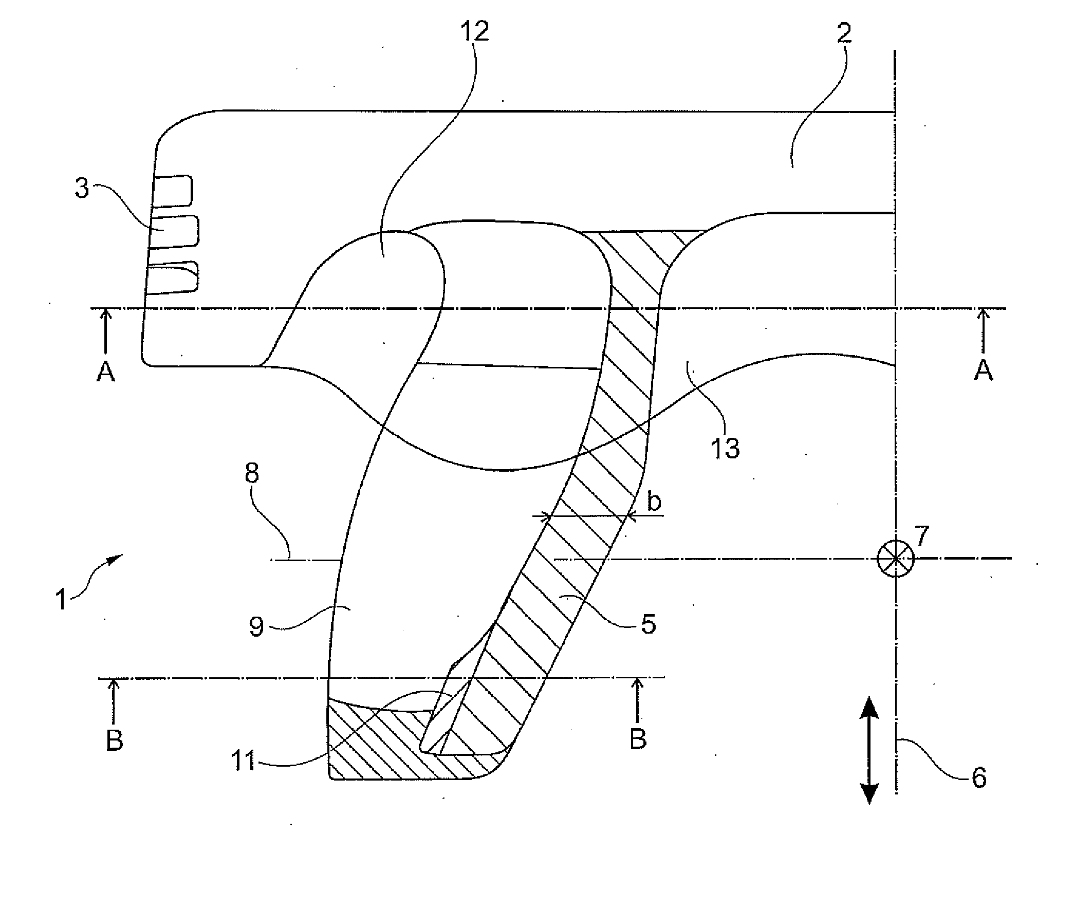
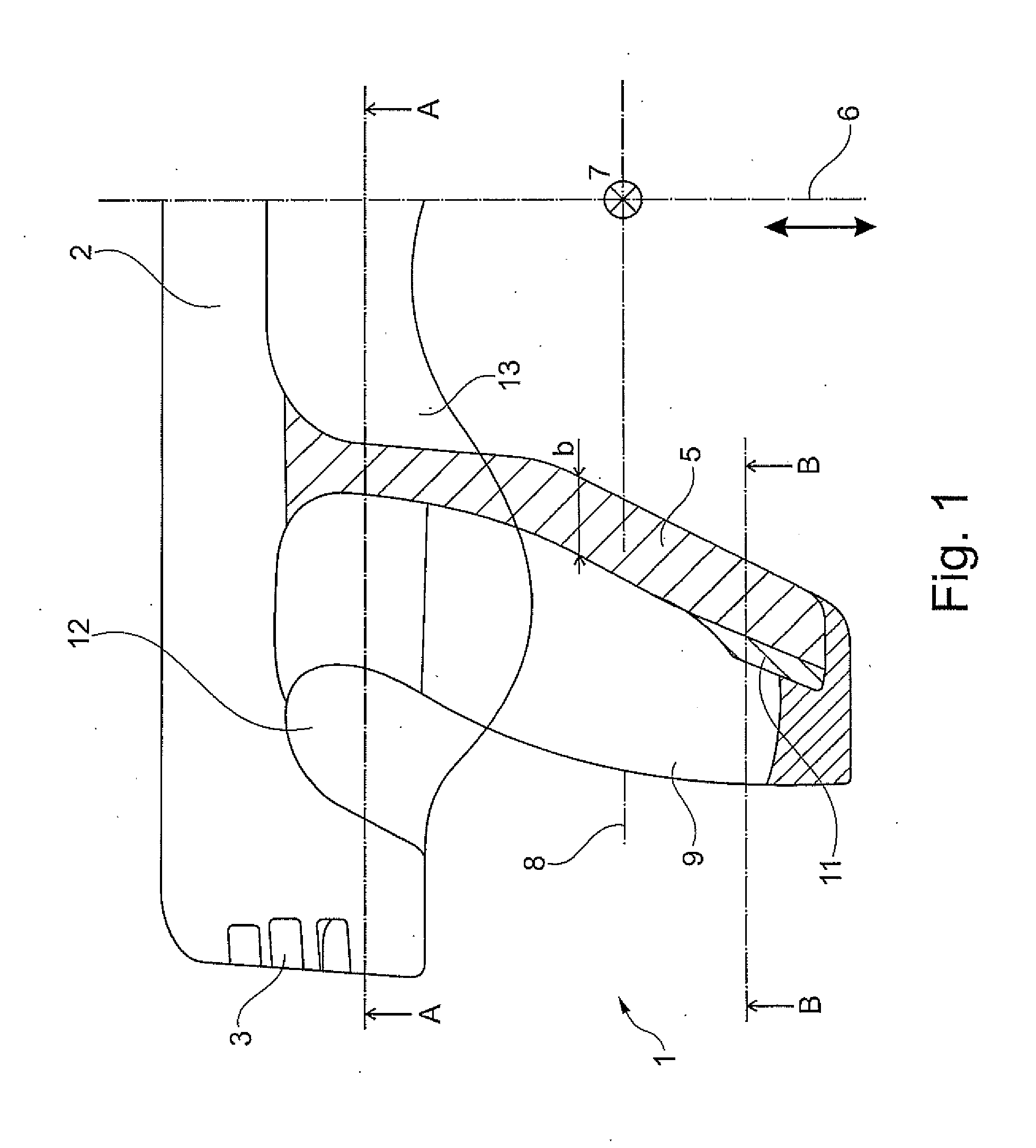
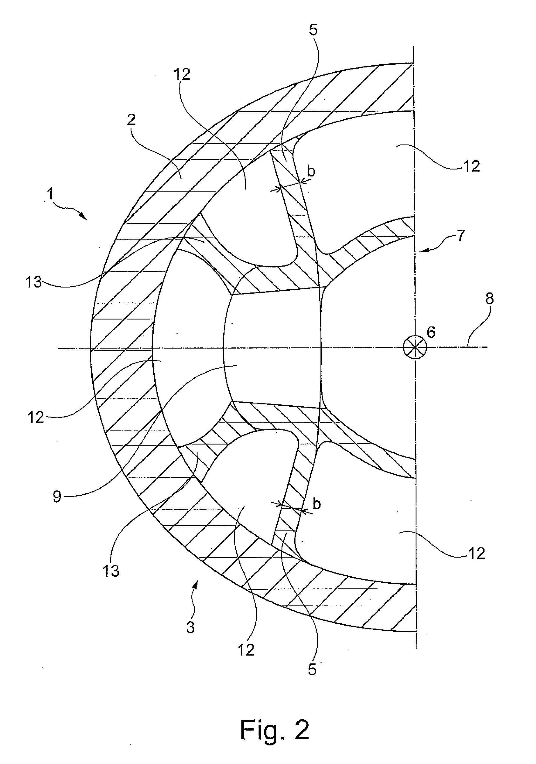
[0043]Only one side of a piston 1 of an internal combustion engine is shown in 1 to 3 as a simplified section. In accordance with FIGS. 1 to 3, only the left side of the piston 1 is shown. In accordance with FIG. 1, the piston 1 is shown in a side view as a cross-section, where the section plane runs through a stroke axis 6 of the piston. In accordance with FIGS. 2 and 3, the section A-A and the section B-B run through a plane that stretches from a piston pin axis 8 and a transverse axis 7 of the piston 1 and is shifted parallel thereto. The transverse axis 7 runs perpendicular to the piston pin axis 8 and the stroke axis 6. In the embodiment the piston 1 is configured as a piston for a spark-ignition internal combustion engine, where the piston 1 is configured as a one-piece component.

[0044]In accordance with FIG. 1, the piston 1 has a piston head 2. The piston head 2 of the piston 1 has a ring zone 3 that completely encircles the piston 1 (shown in simplified form). In accordance ...


PUM


Abstract

The invention relates to a piston (1) of an internal combustion engine, which piston (1) has a piston head (2) with a ring field (3) and a skirt part which is arranged on the piston head (2), wherein the skirt part has at least two load-bearing skirt-wall sections (4a, 4b), and the load-bearing skirt-wall sections (4a, 4b) are connected to one another via at least two obliquely positioned box walls (5) which are set back with respect to the piston external diameter. In each case one pin boss (9) for receiving a piston pin is arranged in the box wall (5) and one skirt-wall section (4a) forms the pressure side and the other skirt-wall section (4b) forms the counter-pressure side. According to the invention that the inner surface of the pin boss (9), in relation to the piston centre, runs flushly with respect to the surface of the associated box wall (5), and the box wall (5) has a concave profile in the transverse extent with respect to the direction of the pin boss (9). Furthermore, the invention relates to a connecting rod of an internal combustion engine.

Description

BACKGROUND[0001]The disclosure relates to a piston of an internal combustion engine, which has a piston head with a ring zone and a skirt section attached to the piston head The disclosure further relates to a connecting rod of an internal combustion engine having a connecting rod to receive a piston pin.[0002]A piston is known from DE 101 45 589 B4 that has a piston head, ring zone and a piston skirt consisting of load-bearing skirt wall sections and recessed connecting walls that connect the skirt wall sections to each other and, in the direction of a piston pin axis, to piston pin bosses recessed from a piston axis that pass through the connecting walls. The connecting walls in this piston are configured convex to an axis in the region of their peripheral lower edge, and in the region of their upper edge below the ring zone concave to the axis, where the width of the skirt wall sections at the lower edge correspond approximately to the width of the skirt wall sections below the r...

Claims


Application Information

Patent Timeline
Patent Type & Authority Applications(United States)
IPC IPC(8): F02F3/00F02F3/02
CPCF02F3/02F02F3/0069F02F3/00F02F3/0076
Inventor GNIESMER, VOLKER
Owner KOLBENSCHMIDT AG
Why Eureka
Try Eureka