Gas barrier film laminate, adhesive film, and electronic component

Inactive Publication Date: 2015-01-29
LINTEC CORP
View PDF4 Cites 3 Cited by
  • Summary
  • Abstract
  • Description
  • Claims
  • Application Information

AI Technical Summary

Benefits of technology

[0019]The gas barrier film laminate according to one aspect of the invention exhibits an excellent gas barrier capability, and rarely shows a deterioration in external appearance (e.g., air bubbles) even when subjected to a high temperature and a high humidity for a long time.
[0020]The pressure-sensitive adh

Problems solved by technology

However, a plastic film easily allows water vapor, oxygen, and the like to pass through as compared w

Method used


Image

  • Gas barrier film laminate, adhesive film, and electronic component
  • Gas barrier film laminate, adhesive film, and electronic component
  • Gas barrier film laminate, adhesive film, and electronic component

Examples


example 1

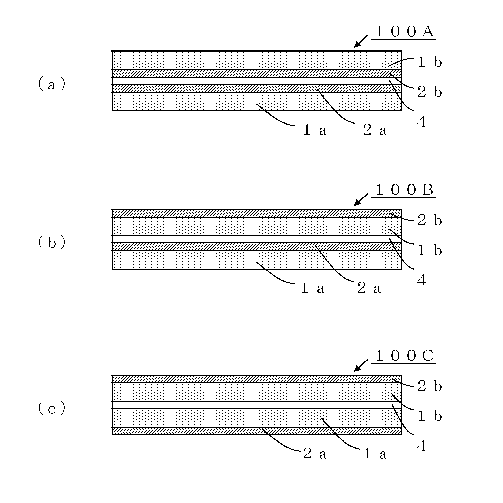
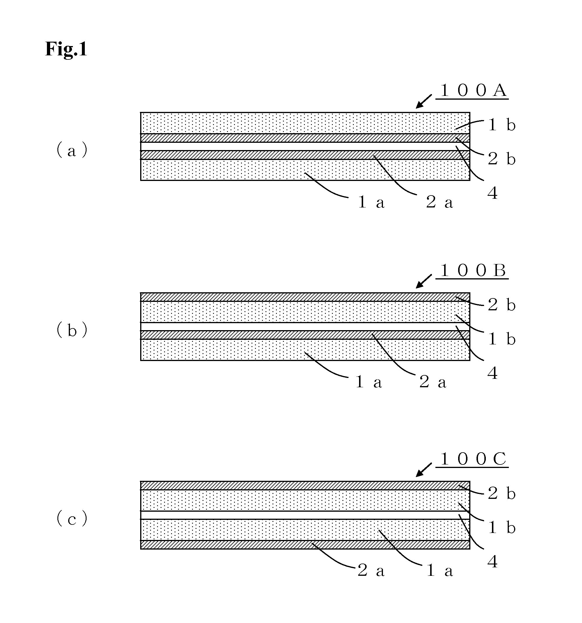
[0256]The pressure-sensitive adhesive composition A was applied to the surface of a release layer of a release film in which a silicone release layer was provided on one side of a polyethylene terephthalate film having a thickness of 38 μm (“SP-PET381031” manufactured by Lintec Corporation) using a comma direct coating method, and dried at 100° C. for 1 minute to form a pressure-sensitive adhesive layer having a thickness of about 10 μm to obtain a release film a provided with the pressure-sensitive adhesive layer. A release film in which a release layer was provided on one side of a polyethylene terephthalate film having a thickness of 38 μm (“SP-PFS50AL-5” manufactured by Lintec Corporation) was separately provided. The release layer of the release film and the pressure-sensitive adhesive layer of the release film a were bonded to obtain a release film A provided with the pressure-sensitive adhesive layer in which the release film was stacked on each side of the pressure-sensitive...

example 2

[0259]A gas barrier film laminate B was produced in the same manner as in Example 1, except that a release film B provided with a pressure-sensitive adhesive layer that was prepared using the pressure-sensitive adhesive composition B instead of the pressure-sensitive adhesive composition A, was used.

example 3

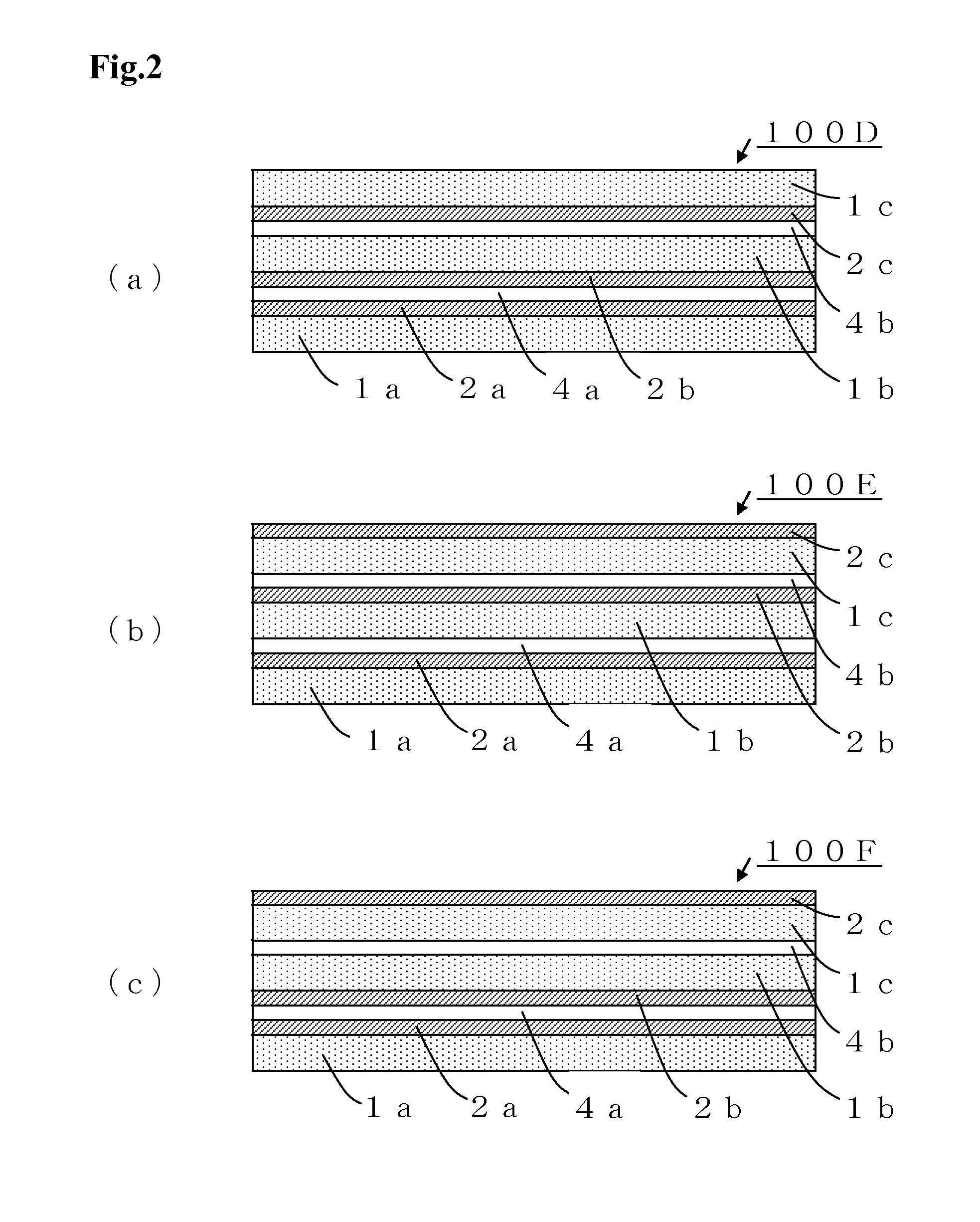
[0263]The gas barrier layer of the gas barrier film produced as described above was bonded to a pressure-sensitive adhesive layer of a sheet provided with a pressure-sensitive adhesive layer in which a urethane-based pressure-sensitive adhesive layer was provided on a release film (“G-6” manufactured by Kurabo Industries, Ltd., thickness: 25 μm) using a heat laminator (lamination temperature: 120° C., speed: 0.24 m / min), and the release film was removed. The exposed urethane-based pressure-sensitive adhesive layer was bonded to the gas barrier layer of another gas barrier film using the heat laminator to produce a gas barrier film laminate F.


PUM

PropertyMeasurementUnit
Temperatureaaaaaaaaaa

Abstract

The present invention relates to a gas barrier film laminate comprising at least two gas barrier films, the gas barrier film laminate having a configuration in which two adjacent gas barrier films are stacked through a pressure-sensitive adhesive layer, and the pressure-sensitive adhesive layer having a shear load reduction ratio α (%) given by an expression (I) in claim 1, of 70% or less; and an adhesive film that is used to produce a gas barrier film laminate that includes at least two gas barrier films, and has a configuration in which two adjacent gas barrier films are stacked through a pressure-sensitive adhesive layer, the adhesive film comprising at least a gas barrier film and a pressure-sensitive adhesive layer that are stacked adjacent to each other, the pressure-sensitive adhesive layer having a shear load reduction ratio α (%) given by an expression (I) in claim 11, of 70% or less. Provided is a gas barrier film laminate that exhibits an excellent water vapor barrier capability, and rarely shows a deterioration in external appearance (e.g., air bubbles) even when subjected to a high temperature and a high humidity for a long time, the adhesive film that is useful for producing the gas barrier film laminate, and an electronic member that includes the gas barrier film laminate.

Description

TECHNICAL FIELD[0001]The invention relates to a gas barrier film laminate that exhibits an excellent gas barrier capability, and includes at least two gas barrier films that are stacked through a pressure-sensitive adhesive layer, a pressure-sensitive adhesive film that is useful for producing the gas barrier film laminate, and an electronic member that includes the gas barrier film laminate.BACKGROUND ART[0002]Use of a transparent plastic film as a substrate for an electronic member (e.g., solar cell, liquid crystal display, or electroluminescence (EL) display) instead of a glass sheet (plate) has been studied in order to implement a reduction in thickness, a reduction in weight, flexibility, impact resistance, and the like.[0003]However, a plastic film easily allows water vapor, oxygen, and the like to pass through as compared with a glass sheet, and may easily cause a deterioration in elements provided in an electronic member.[0004]In order to solve the above problem, Patent Docu...

Claims


Application Information

Patent Timeline
IPC IPC(8): B32B27/08C09J7/00B32B27/30B32B7/12B32B27/36C09J7/22C09J7/25C09J7/38
CPCB32B27/08B32B7/12B32B27/36B32B27/30C09J7/00B32B2307/7246C09J133/08B32B2255/102B32B2457/00C09J2433/00C09J2475/00C09J175/04B32B2307/7242C08L75/04C09J2203/326C09J2483/006C09J133/066B32B2255/10B32B2255/26B32B2405/00B32B2457/12B32B2457/20C08G18/6229C08G18/6254C08G2170/20C08J5/128C08J7/123C08J2383/08C08J2433/06C09J7/38C09J7/22C09J7/25Y10T428/31598Y10T428/31663Y10T428/24942Y10T428/263Y10T428/2835C09J2301/312C08F220/1808C08F220/1807C08F220/20C08F220/1804C08F220/06C08F220/14B32B17/10C09J201/00
Inventor KENMOCHI, SUGURUNAGANAWA, SATOSHINAGAMOTO, KOICHI
Owner LINTEC CORP
Why Eureka
Try Eureka