
Gas barrier laminate, method for producing same, member for electronic devices, and electronic device

Active Publication Date: 2015-04-09
LINTEC CORP
View PDF4 Cites 21 Cited by
  • Summary
  • Abstract
  • Description
  • Claims
  • Application Information

AI Technical Summary

Benefits of technology

The gas barrier laminate described in this patent has excellent gas barrier capability, durability, and winding capability even after being exposed to high temperatures and humidity for a long time. The production method described in the patent prevents winding failure when rolling up a long gas barrier laminate, allowing for efficient and continuous production. The electronic device member described in the patent is suitable for use in flexible displays and solar cells due to its excellent gas barrier capability and durability.

Problems solved by technology

However, the gas barrier film may show a deterioration in gas barrier capability due to a deterioration in the base film through thermal shrinkage when subjected to a high temperature and a high humidity for a long time.
However, when using an inorganic deposited layer as the gas barrier layer, cracks may occur in the gas barrier layer, and a deterioration in gas barrier capability may occur when the gas barrier film is rolled or bent due to low flexibility.
However, the above gas barrier film exhibits improved flexibility, but may show a deterioration in gas barrier capability through cure shrinkage of the gas barrier layer when subjected to a high temperature and a high humidity for a long time.
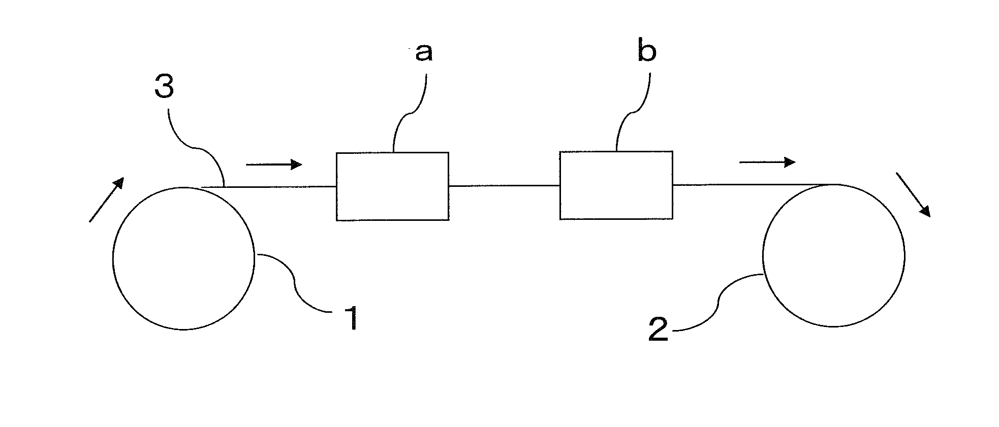
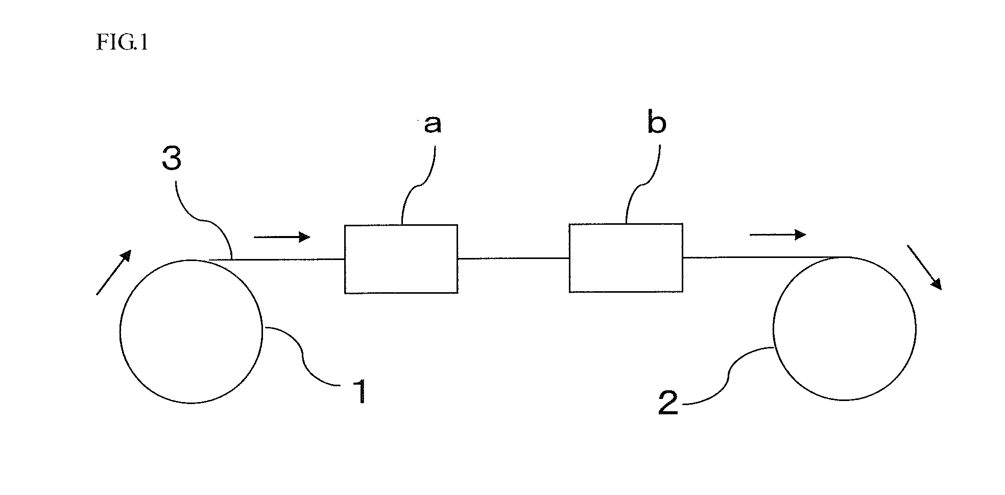
When producing a long gas barrier film using a roll-to-roll method, winding failure such as blocking (i.e., the front surface and the back surface of the film adhere to each other) or wrinkles may occur when winding the gas barrier film.

Method used


Image

  • Gas barrier laminate, method for producing same, member for electronic devices, and electronic device
  • Gas barrier laminate, method for producing same, member for electronic devices, and electronic device

Examples


example 1

[0133]The primer layer-forming solution A was applied to a PET film (“PET25 T-100” manufactured by Mitsubishi Plastics, Inc., thickness: 25 μm, hereinafter referred to as “PET film A”) using a bar coater, and heated (dried) at 70° C. for 1 minute. UV rays were applied to the primer layer-forming solution A (high-pressure mercury lamp, line speed: 20 m / min, cumulative intensity: 100 mJ / cm2, peak intensity 1.466 W, pass count: 2) using a UV-ray irradiation line to form a primer layer having a thickness of 1 μm.

[0134]The modulus of elasticity of the primer layer at 90° C. was 3.59 GPa.

[0135]The modulus of elasticity was measured using the following method.

Modulus of Elasticity

[0136]The modulus of elasticity (GPa) of the surface of the primer layer at 25° C., 60° C., and 90° C. was measured by a nanoindentation method using a nanohardness tester (“DUH-W201-S” manufactured by Shimadzu Corporation). The measurement results are shown in Table 1.

[0137]A perhydropolysilazane (“AZNL110A-20” m...

example 2

[0141]A laminate 2 was produced in the same manner as in Example 1, except that the primer layer-forming solution B was used instead of the primer layer-forming solution A.

example 3

[0142]A laminate 3 was produced in the same manner as in Example 1, except that the primer layer-forming solution C was used instead of the primer layer-forming solution A.


PUM

PropertyMeasurementUnit
Temperatureaaaaaaaaaa
Thicknessaaaaaaaaaa
Pressureaaaaaaaaaa

Abstract

The present invention provides: a gas barrier laminate comprising a base, a primer layer, and a gas barrier layer, the primer layer and the gas barrier layer being sequentially stacked on at least one side of the base, the primer layer having a modulus of elasticity at 90° C. of 1.6 GPa or more, and a coefficient of static friction between a surface of one side of the gas barrier laminate and a surface of the other side of the gas barrier laminate being 0.35 to 0.8; a method for producing the gas barrier laminate; an electronic device member comprising the gas barrier laminate; and an electronic device.

Description

TECHNICAL FIELD[0001]The invention relates to a gas barrier laminate, a method for producing the same, an electronic device member that includes the gas barrier laminate, and an electronic device that includes the electronic device member.BACKGROUND ART[0002]In recent years, a gas barrier film in which an inorganic deposited (evaporated) layer (gas barrier layer) is stacked on a transparent plastic film has been used instead of a glass sheet as an electrode substrate for displays (e.g., liquid crystal display and electroluminescence (EL) display) in order to implement a reduction in thickness, a reduction in weight, flexibility, and the like.[0003]However, the gas barrier film may show a deterioration in gas barrier capability due to a deterioration in the base film through thermal shrinkage when subjected to a high temperature and a high humidity for a long time.[0004]A method that stacks the gas barrier layer on the base film through a primer layer to prevent a deterioration in ga...

Claims


Application Information

Patent Timeline
IPC IPC(8): C09D5/00C23C14/58B05D3/12C23C14/48C08J7/043C08J7/044C08J7/048
CPCC09D5/00B05D3/12C23C14/5886C23C14/48B32B27/08B32B2307/7244C08J7/18C08J2367/02C08J2433/08C08J2433/10C08J2433/12C08J2483/04C08J2483/16Y10T428/24355C08J7/0423C08J7/048C08J7/043C08J7/044C08J7/042
Inventor SUZUKI, YUUTANAGAMOTO, KOICHIKONDO, TAKESHI
Owner LINTEC CORP
Learn More