Slew rate control device using switching capacitor

Inactive Publication Date: 2015-02-05
FOUND OF SOONGSIL UNIV IND COOP
View PDF4 Cites 1 Cited by
  • Summary
  • Abstract
  • Description
  • Claims
  • Application Information

AI Technical Summary

Benefits of technology

The present invention provides a slew rate control device using a switching capacitor without the need for an additional control circuit. The device includes a first capacitor that controls the rising slope of a signal output from a target circuit when the clock signal is high, a switch that controls the falling slope of the signal output when the clock signal is low, and a second capacitor that controls the falling slope when the clock signal is low. The capacitances of the first and second capacitors can be controlled to equal the rising and falling slopes. The device also includes a sensing unit that detects the rising and falling slopes and a control unit that determines the capacitance of the first or second capacitor and sends a capacitance control signal to the appropriate capacitor. The first and second capacitors can be variable or formed as capacitor banks with different capacitances. The technical effect of this invention is to provide a simple and effective way to control the slew rate of a circuit without the need for additional components.

Problems solved by technology

Further, when the rising slope and the falling slope are not identical, quality of the signal may be degraded.
In the related art, in order to solve an unbalance problem of the slew rate, an additional control circuit that controls the slew rate is needed, so that the circuit may be complicated due to the additional control circuit.

Method used


Image

  • Slew rate control device using switching capacitor
  • Slew rate control device using switching capacitor
  • Slew rate control device using switching capacitor

Examples


Embodiment Construction

[0038]Exemplary embodiments of the present invention will now be described in detail with reference to the accompanying drawings.

[0039]As set forth above, according to exemplary embodiments of the invention, it is possible to easily design a circuit without requiring a complicated control circuit by simply a switching capacitor to a power supply node or a ground node of a target circuit to control a slew rate.

[0040]Exemplary embodiments of the present invention will be described in detail with reference to the accompanying drawings to allow those skilled in the art to easily implement the present invention.

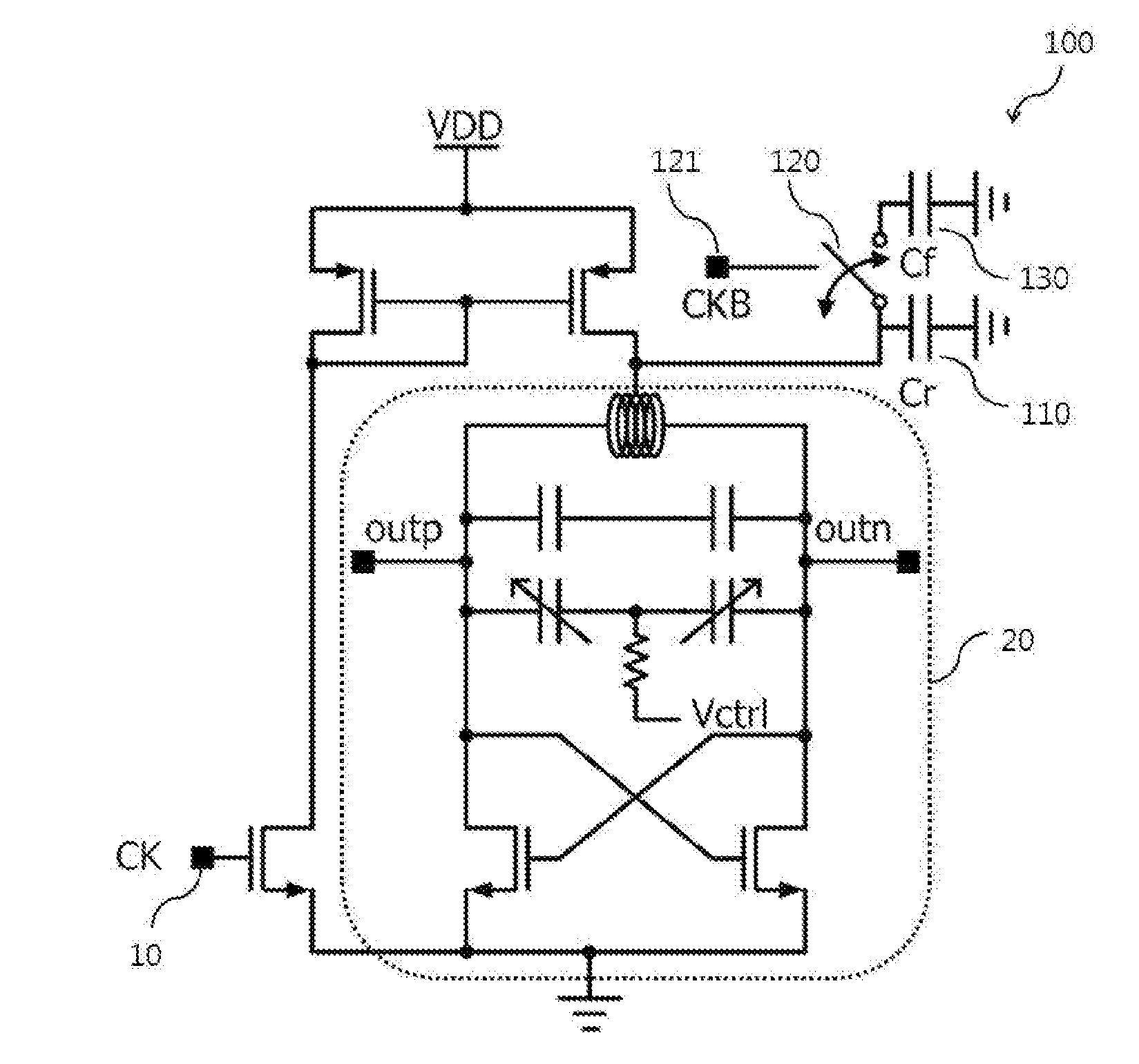
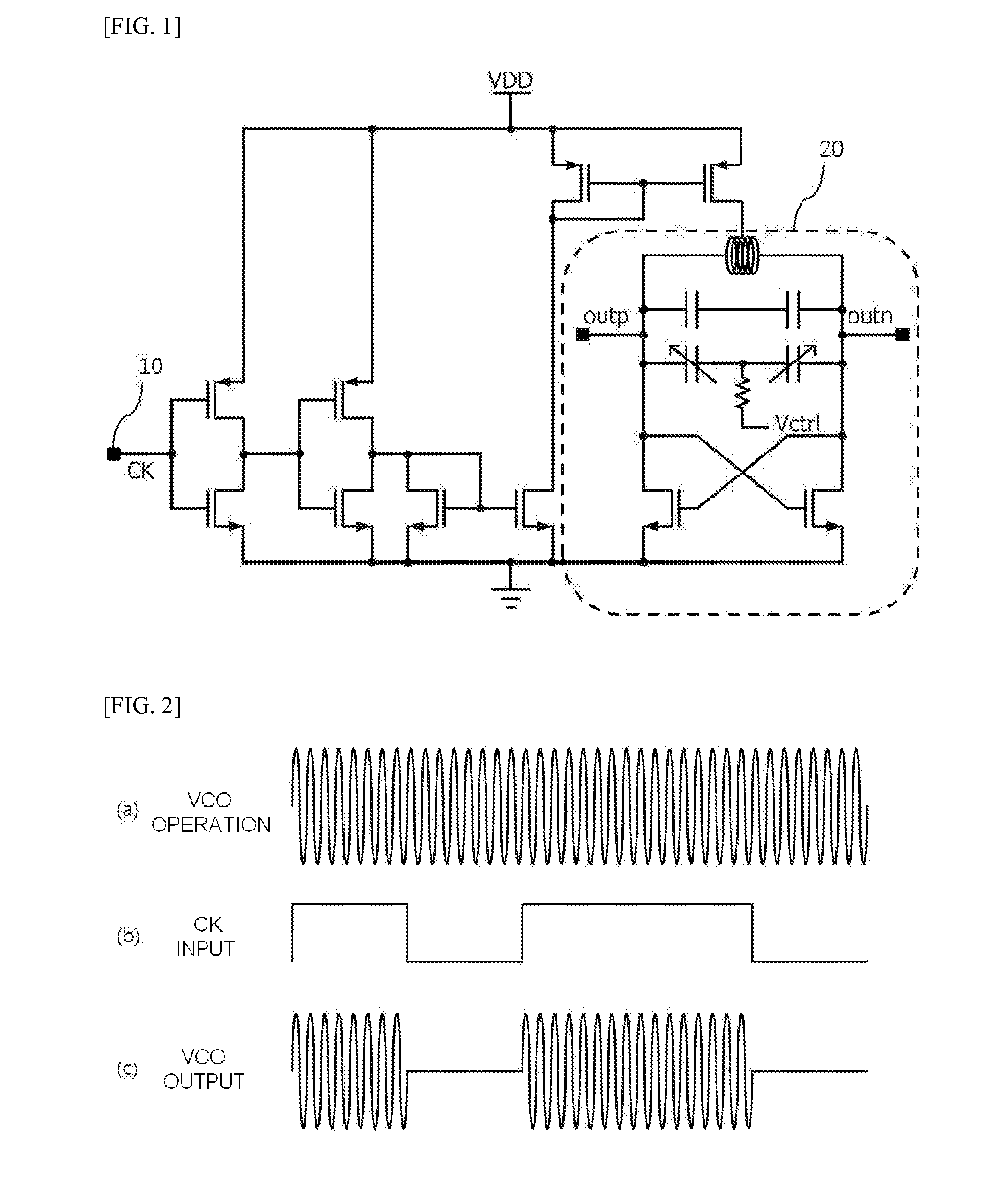
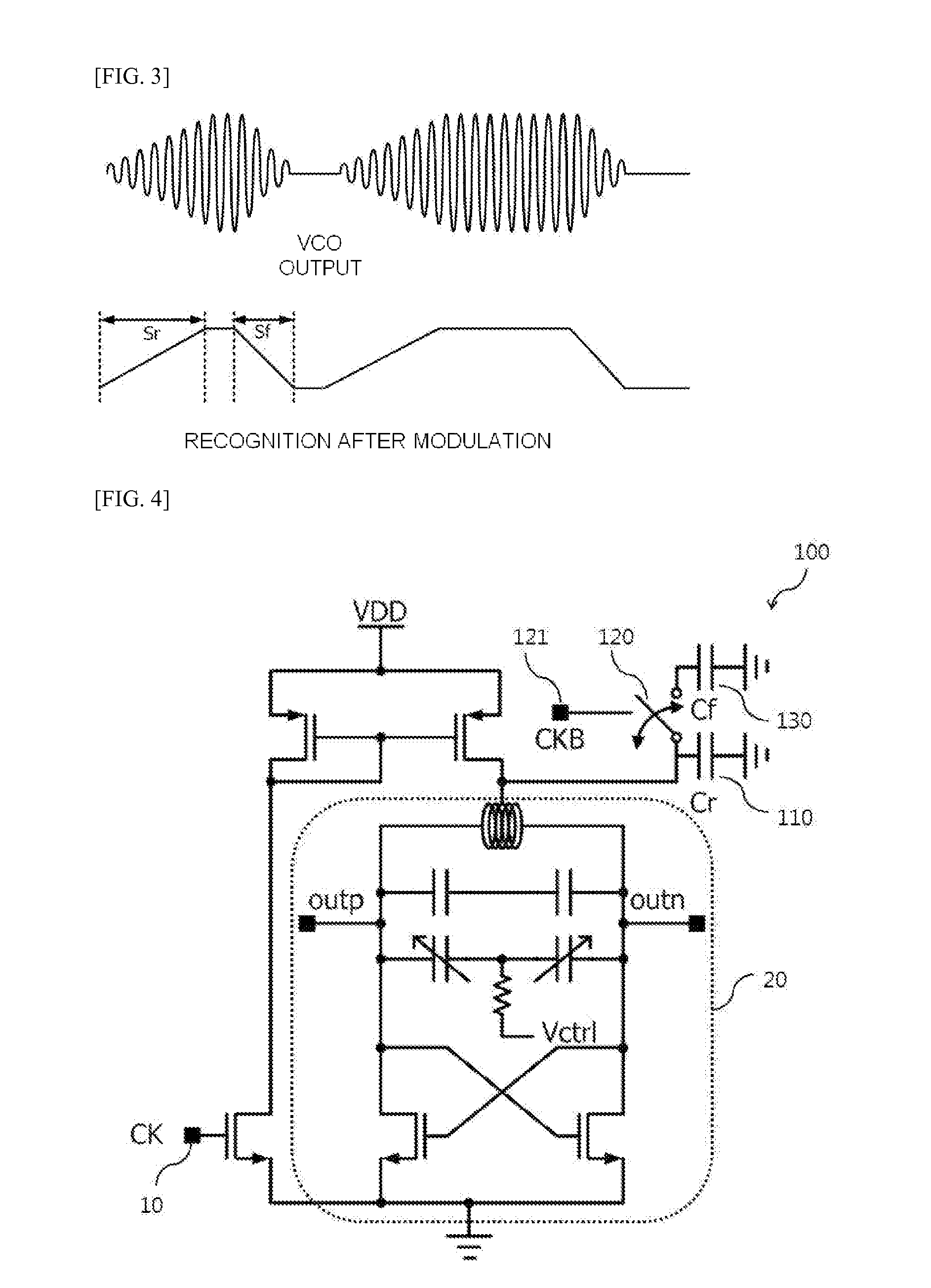
[0041]The present invention relates to a slew rate control device using a switching capacitor, and the slew rate control device is connected to a power supply node or a ground node of a target circuit such as a voltage controlled oscillator or an amplifier to effectively control a rising slope and a falling slope generated in an output signal of the target circuit. Here, an operat...


PUM


Abstract

Disclosed is a slew rate control device using a switching capacitor which includes a first capacitor that is connected to a target circuit operated in response to a clock signal, and controls a rising slope of a signal output from the target circuit when the clock signal is in a high state; a switch that is connected to the first capacitor in parallel, receives a reverse signal of the clock signal, as a control signal, and is turned on when the clock signal is in a low state; and a second capacitor that is connected to the switch in series, and controls a falling slope of the signal output from the target circuit when the clock signal is in the low state.

Description

CROSS-REFERENCE TO RELATED APPLICATIONS[0001]This application claims the priority of Korean Patent Application No. 10-2013-0092749 filed on Aug. 5, 2013, in the Korean Intellectual Property Office, the disclosure of which is incorporated herein by reference.BACKGROUND OF THE INVENTION[0002]1. Field of the Invention[0003]The present invention relates to a slew rate control device using a switching capacitor, and more particularly, to a slew rate control device using a switching capacitor with which it is possible to control rising and falling slew rates by turning on and off a signal in an amplitude shift keying process.[0004]2. Description of the Related Art[0005]In general, a slew rate means the amount of change in rising and falling of an output per unit time with respect to a step change of a control input signal. The slew rate has a characteristic that sensitively responds to influence of an external environment or a temperature.[0006]FIG. 1 is a circuit diagram of a voltage con...

Claims


Application Information

Patent Timeline
IPC IPC(8): H03K5/04
CPCH03K5/04H03B5/12
Inventor CHO, SEONG WOONGSHIN, HOO YOUNGPARK, CHANG KUN
Owner FOUND OF SOONGSIL UNIV IND COOP
Why Eureka
Try Eureka