
Phased-array RF pulse generator

a phased array and pulse generator technology, applied in the field of phasedarray radiofrequency (rf) pulse generator control, can solve the problems of increasing the upper limit of the generated frequency and operating rf voltage of the transmission line, difficult to determine the phase and frequency of each rf source, and individual adc devices currently limited to sampling rates of about 4 gs/s

Active Publication Date: 2015-02-05
MBDA UK
View PDF3 Cites 1 Cited by
  • Summary
  • Abstract
  • Description
  • Claims
  • Application Information

AI Technical Summary

Benefits of technology

This patent describes a method for monitoring and adjusting the timing of video pulses in an RF generator to ensure they have the desired phase relationship. This allows for the adjustment of RF sources in a large array, resulting in improved performance and reliability. The technical effect of this patent is the improved synchronization and timing control of RF sources in video-to-RF conversion systems.

Problems solved by technology

This arrangement reduces the effects of stray capacitances and stray inductances, and thereby increases the upper limit of the generated frequency and operating RF voltage of the transmission line.
The short duration of the RF signal makes it difficult to determine the phase and frequency of each RF source.
Individual ADC devices are currently limited to sampling rates of about 4 GS / s.
Those techniques require relatively expensive systems that are suitable for monitoring only relatively small numbers of RF sources.
However, large transmitter arrays require a significant number of measurement channels (much more than 10 elements), for which an ADC-based control system is both bulky and costly (typically several tens of thousands of pounds).

Method used


Image

  • Phased-array RF pulse generator
  • Phased-array RF pulse generator
  • Phased-array RF pulse generator

Examples


Embodiment Construction

[0040]In an example embodiment of the invention, the output frequencies and output phases of an array of microwave pulse generators are controlled.

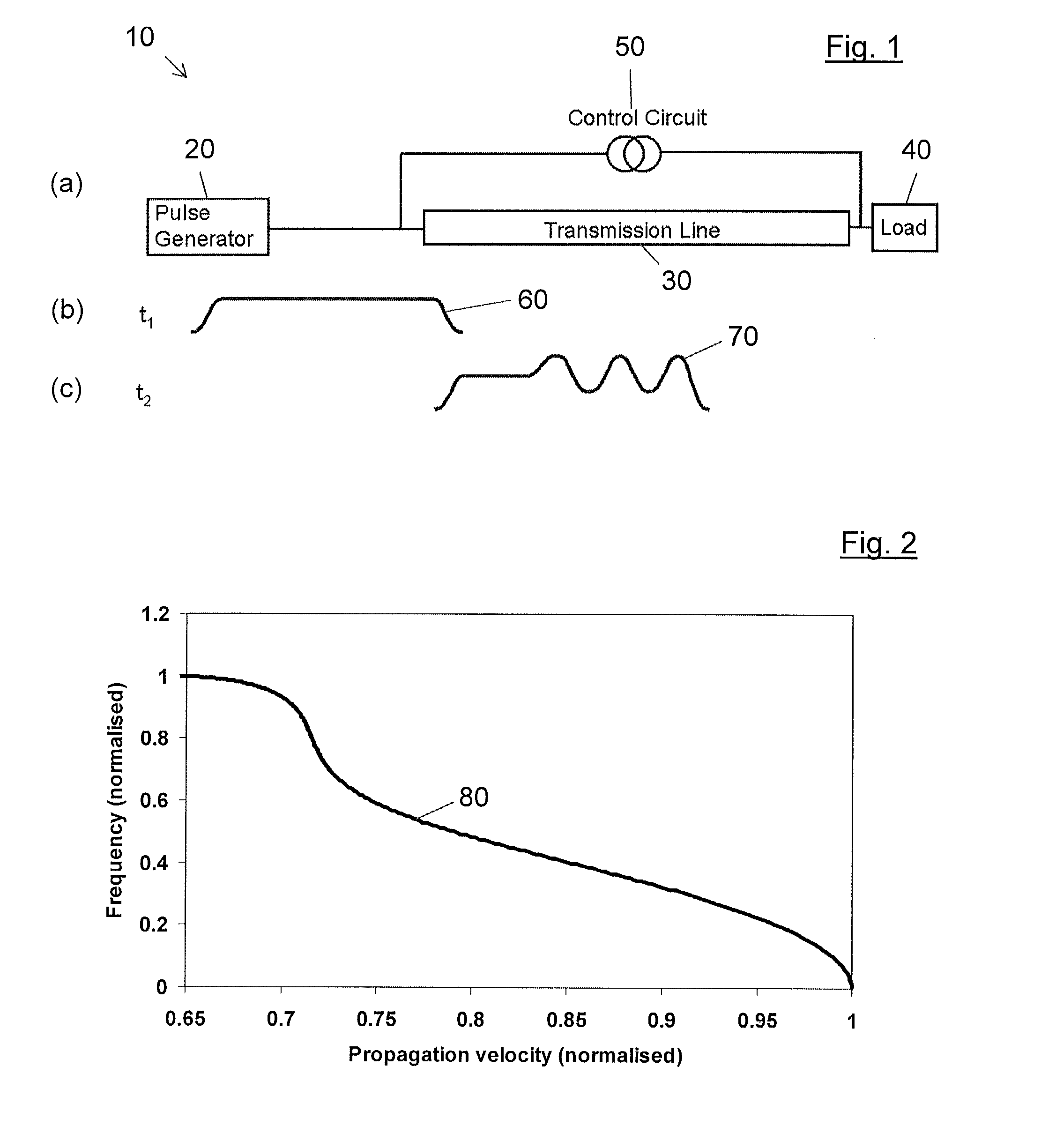
[0041]A prior-art microwave pulse generator 10 (FIG. 1(a)), of the type described above, and in GB 2368213A (BAE Systems plc), comprises a video pulse generator 20 connected to a nonlinear, dispersive transmission line 30, which is in turn connected to a load 40. The nonlinearity of the transmission line, and hence the frequency of microwave pulses generated therein, is controlled by a control circuit 50. The video pulse generator 20 generates an electrical video pulse, i.e. a pulse 60 having the form shown schematically in FIG. 1(b). The nonlinearity and dispersion of the transmission line 30 result in the pulse shape shifting to that of a video pulse 70 carrying a microwave-frequency modulation. The dispersion curve 80 (FIG. 2) of the transmission line 30 (i.e. the variation of oscillation frequency with phase velocity) is a monotonical...


PUM


Abstract

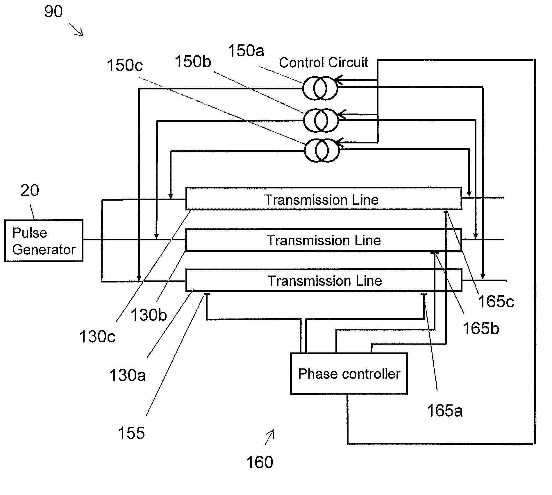
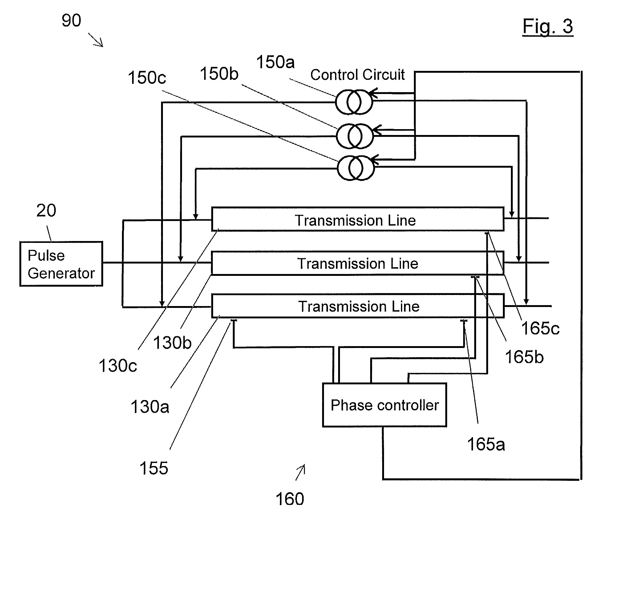
A phased-array RF pulse generator is disclosed which includes a video-pulse generator arranged to generate video pulses each having a leading edge. An array of nonlinear and dispersive transmission lines, are arranged to generate RF pulses from the video pulses. At least one sensor is arranged to detect the leading edge of the video pulses after they have passed along the transmission lines. A phase controller is arranged to set the velocity of the video pulses in each transmission line to put the detected leading edges, and hence the generated RF pulses, into a desired phase relationship.

Description

FIELD OF THE INVENTION[0001]This invention relates to the field of phased-array radio-frequency (RF) pulse generators. The invention relates especially to control of pulsed RF generators, and more particularly to phase and / or frequency control of arrays of pulsed RF generators that have dispersive characteristics. The invention relates more especially to RF pulse generator arrays based on nonlinear and dispersive RF-generating transmission lines.BACKGROUND ART[0002]In the prior art, circuits are described that use nonlinear and dispersive transmission lines to produce pulsed RF signals. (As used herein, the terms radio frequency (or RF) refers to microwave or longer electromagnetic waves.) An electrical pulse is injected into such a transmission line, and the nonlinear and dispersive characteristics of the line act to form a high-frequency signal as the pulse propagates along the transmission line. Several different types of nonlinear material and several types of dispersive charact...

Claims


Application Information

Patent Timeline
IPC IPC(8): H04B3/04
CPCH03K5/01H03H11/18H03K3/45H03K3/80G01S7/282G01S13/4463H01Q3/30H03B19/03
Inventor SEDDON, NIGELMASON, PHILIP LESLIEOWEN, MARK
Owner MBDA UK
Learn More