Slotline antenna

a technology of slotline antennas and antennas, which is applied in the direction of slot antennas, instruments, measurement devices, etc., can solve the problems of unbalanced feeding of cables and electrically short antennas, and the typical poor reflection coefficient of electrical short antennas at feeding ports, so as to reduce the dispersion of antennas, prevent unnecessary circuit board area, and reduce the effect of antenna dispersion

Active Publication Date: 2015-02-05
ROHDE & SCHWARZ GMBH & CO KG
View PDF13 Cites 16 Cited by
  • Summary
  • Abstract
  • Description
  • Claims
  • Application Information

AI Technical Summary

Benefits of technology

[0014]According to a tenth advantageous aspect of the present invention, the antenna elements are also formed by a metallization layer on a circuit board. The antenna elements comprise radiating edges. The shape of the circuit board follows the shape of the radiating edges of the antenna elements in general and extends beyond the radiating edges slightly. The antenna elements are therefore ideally supported by the circuit board. Detrimental effects by unnecessary circuit board area are prevented which reduces dispersion in antenna. By cutting the circuit board in the slot between the antenna elements the ratio of the signal power propagating in the surrounding air to the signal power propagating in the circuit board is increased. Then the transmission line medium becomes more uniform and dispersion effect is reduced. This prevents directivity drop especially at the higher bound of frequency range.
[0015]According to an eleventh advantageous aspect of the invention, an antenna system comprises two previously described antennas. The two antennas are mounted perpendicularly, intersecting along a symmetry axis between their antenna elements. The two planar antenna elements form a three-dimensional antenna system. When using only one of the previously described antennas, a linear polarization of the emitted signal is achieved. By use of a here described antenna system, it is possible to achieve arbitrarily polarized electromagnetic emission or two orthogonal linear polarizations. Alternatively by adding a 90° phase shift between the signals of the two antennas, it is possible to reach a circular-polarized emitted signal.
[0016]According to a twelfth advantageous aspect, the antenna system comprises a base plate mounted perpendicularly to both antennas on a non-radiating side of the antennas and absorbers mounted on the base plate, advantageously extending in the direction towards a radiating side of the antenna. Undesired cross-effects between the two antennas and reflection from the base plate can therefore be prevented.
[0017]In an advantageous thirteenth aspect, an antenna comprises two antenna elements forming a planar slotline antenna. The antenna elements are formed by a metallization layer on a circuit board. The antenna elements in this case comprise radiating edges. The shape of the circuit board follows the shape of the radiating edges and extends beyond the radiating edges slightly. As described earlier, a high directivity can be achieved by reduction of signal dispersion.
[0018]In a fourteenth advantageous aspect of the present invention, a measurement chamber for measuring emissions of a wireless device comprises a container sealed against electromagnetic radiation and a previously described antenna or antenna system. The device under test is placed within the test chamber and can easily be measured. The test chamber can have a low size, since the inventive antenna and antenna system only require a small space.
[0019]The motivation for introducing the absorbers is to advantageously dampen all other modes except the slotline mode. At the frequencies where an antenna width W or an antenna length L are longer as λ / 2, some parasitic electromagnetic modes might be excited along the metallic edges of the antenna. The absorbers shall dampen these modes as well. As a result broad bandwidth, high directivity and low reflection coefficient is maintained.

Problems solved by technology

Thus, the cable provides unbalanced feeding and becomes an antenna part, too.
Furthermore the electrically short antenna provides typically poor reflection coefficient at the feeding port.

Method used


Image

  • Slotline antenna
  • Slotline antenna
  • Slotline antenna

Examples


first embodiment

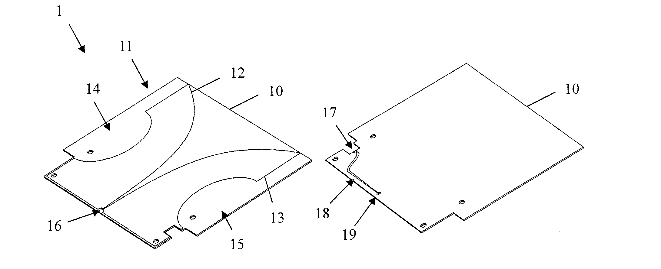
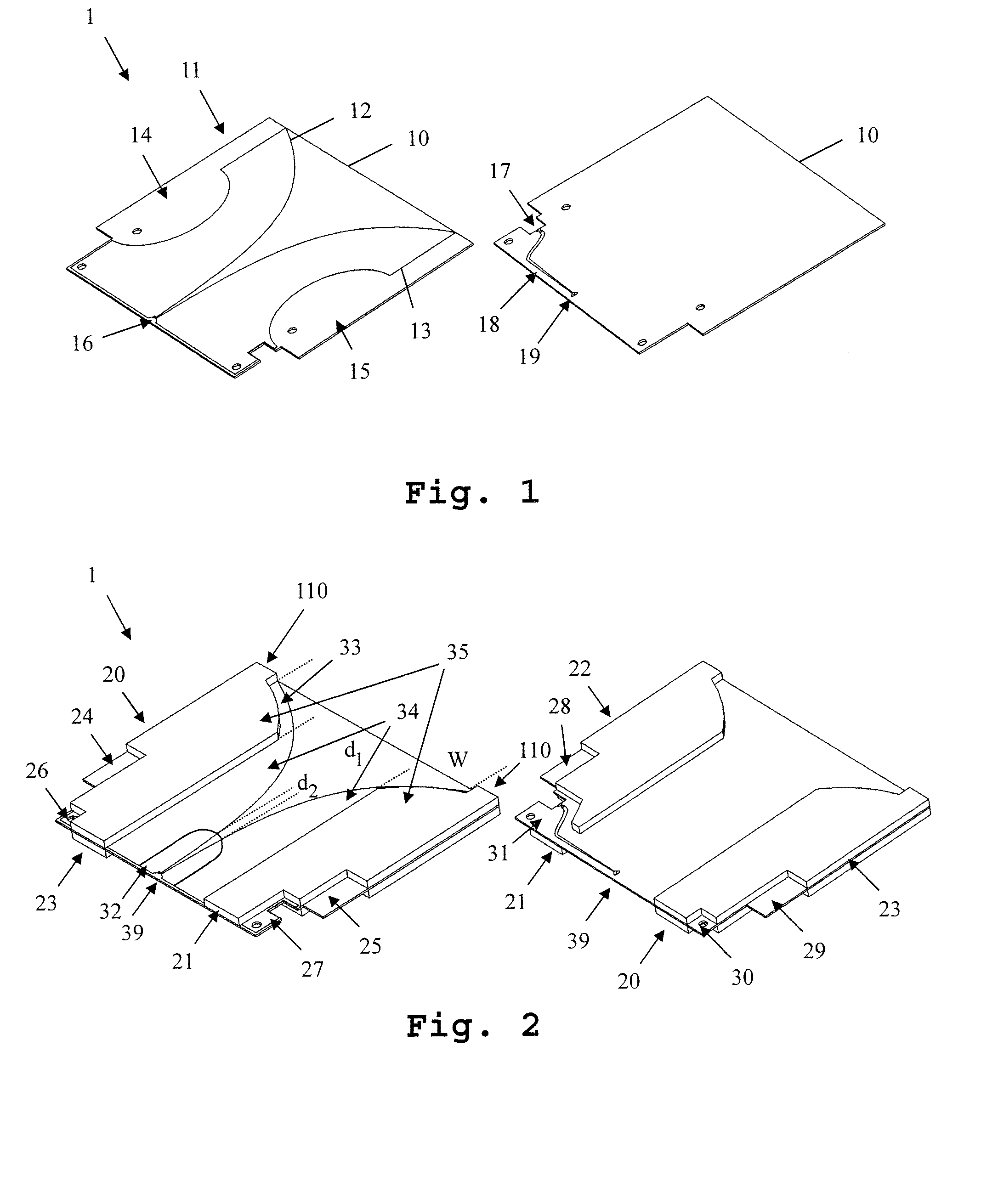
[0032]FIG. 1 shows a first embodiment of the inventive antenna 1. In FIG. 1, for reasons of clarity and comprehensibility, not all components of the antenna have been depicted. In FIG. 2, a view of the antenna showing all components is depicted. On the left side of the FIG. 1, a front-view of the antenna 1 is shown. On the right side, a back-view of the antenna 1 is shown.

[0033]The antenna 1 comprises a circuit board 10 and two antenna elements 12, 13 formed in a metallization layer 11 on the front side of the circuit board 10. The antenna elements 12, 13 are not connected electrically. The antenna element 13 is directly connected to a connector 17, while the antenna element 12 is connected to the connector 17 through a wire 19 and a feed line 18. The connector 17 is for example a coaxial connector. The antenna element 13 in this case is connected to the shielding of the coaxial connector, while the antenna element 12 is connected to the center line of the coaxial connector 17.

[0034...

second embodiment

[0045]In FIG. 6, a second embodiment of the inventive antenna is shown. In this embodiment, the antenna 2 does not necessarily comprise absorber elements. The circuit board 70 of the antenna 2 here furthermore comprises a recess 72 at the emitting side of the antenna 2. The shape of the circuit board 70 follows the shape of emitting edges 71 of the antenna elements. The circuit board 72 though extends beyond the shape of the antenna elements into the emitting direction of the antenna slightly. A current flowing in the antenna elements at the emitting edge of the antenna elements results in an electromagnetic field along the emitting edge of the antenna elements being present in the surround air and in the circuit board dielectric. These two media have different electrical permittivity creating dispersion effect. The cut 72 reduces the dispersion and increase radiation directivity.

[0046]Moreover, in FIG. 7, the absolute gain 111 of an embodiment as shown in FIG. 6 is depicted. Gain d...

third embodiment

[0048]In FIG. 8, a third embodiment of an inventive antenna 83 is shown. The antenna 83 is part of an antenna system 3 which is comprised by the antenna 83, a base plate 80, on which the antenna 83 is mounted perpendicularly, an absorber base 81 mounted on the base plate 80 and a plurality of absorbers mounted on the absorber base 81. The absorbers 82 extend from a non-emitting side of the antenna towards the emitting side of the antenna 83 and are mounted parallel to the antenna. The absorbers advantageously are shorter than the antenna 83. The antenna 83 is an antenna according to one of the previously shown embodiments of the inventive antenna.


PUM


Abstract

An inventive antenna comprises two antenna elements forming a planar slotline antenna. The antenna furthermore comprises absorber elements surrounding the antenna elements on two layers. The absorber elements are shaped to partially cover the antenna elements and partially not cover the antenna elements. Moreover, they are shaped to dampen at least a dipole-mode of the antenna elements and not to dampen a slotline-mode of the antenna elements.

Description

FIELD OF THE INVENTION[0001]This invention relates to an improved slotline antennaBACKGROUND OF THE INVENTION[0002]For creating broadband antennas with low production costs, conventionally Vivaldi-antennas are used. Vivaldi-antennas consist of a tapered slotline antenna on a circuit board. Regular Vivaldi-antennas though create an electrically short antenna with a dipole-mode of radiation at signal frequencies where the antenna width W is approximately shorter than half of the signal wave length (W<λ / 2). At those frequencies, unwanted radio frequency currents flow on the outer shield of the feeding coaxial cable. Thus, the cable provides unbalanced feeding and becomes an antenna part, too. This deforms the radiation pattern towards a dipole-like radiation pattern. For example, the European Patent EP 1 425 818 B1 shows such a Vivaldi-antenna. Furthermore the electrically short antenna provides typically poor reflection coefficient at the feeding port.[0003]Accordingly, the object ...

Claims


Application Information

Patent Timeline
Patent Type & Authority Applications(United States)
IPC IPC(8): H01Q13/10G01R29/10
CPCG01R29/105H01Q13/106H01Q13/085H01Q17/001H01Q17/008H01Q21/24G01R29/0878
Inventor TANKIELUN, ADAM
Owner ROHDE & SCHWARZ GMBH & CO KG
Why Eureka
Try Eureka