
Magnetic resonance device

a magnetic resonance and device technology, applied in the field of magnetic resonance devices, can solve the problems of bone structure, ultrasound imaging does not provide a great deal of information during the birth, and the body region for which magnetic resonance recordings are produced is generally difficult to access from the outside, so as to reduce the homogeneity of the imaging region, improve the accessibility to the body region, and free up spa

Inactive Publication Date: 2015-02-05
SIEMENS AG
View PDF2 Cites 5 Cited by
  • Summary
  • Abstract
  • Description
  • Claims
  • Application Information

AI Technical Summary

Benefits of technology

The patent describes a new shape of a gradient coil used in magnetic resonance imaging (MRI) that helps to generate powerful and linear gradient fields. The gradient coil is shaped like a dish with a base located on the side facing the main field magnet. This design allows for better accessibility from above to the body region of the patient being examined and ensures a symmetrical arrangement in relation to the main field magnet. The technical effects of this new shape are improved MRI image quality and reduced patient discomfort.

Problems solved by technology

Therefore, the body region for which magnetic resonance recordings are being produced is generally hard to access from the outside and spatially restricted.
Although many risk factors for problems during the birth are detected by means of ultrasound before the birth, ultrasound imaging does not provide a great deal of information during the birth.
One reason for this is that bone structures, for example the pelvis, impede propagation of the ultrasound waves.
Therefore, only quite a low homogeneity of the imaging region of the magnet volume is often required for this specific application.
The static field gradient of the magnet volume in the imaging region can be limited.
The switchable coils may not have the purpose of exciting the spins in the imaging region or the purpose of receiving magnetic resonance signals.

Method used


Image

  • Magnetic resonance device
  • Magnetic resonance device
  • Magnetic resonance device

Examples


first embodiment

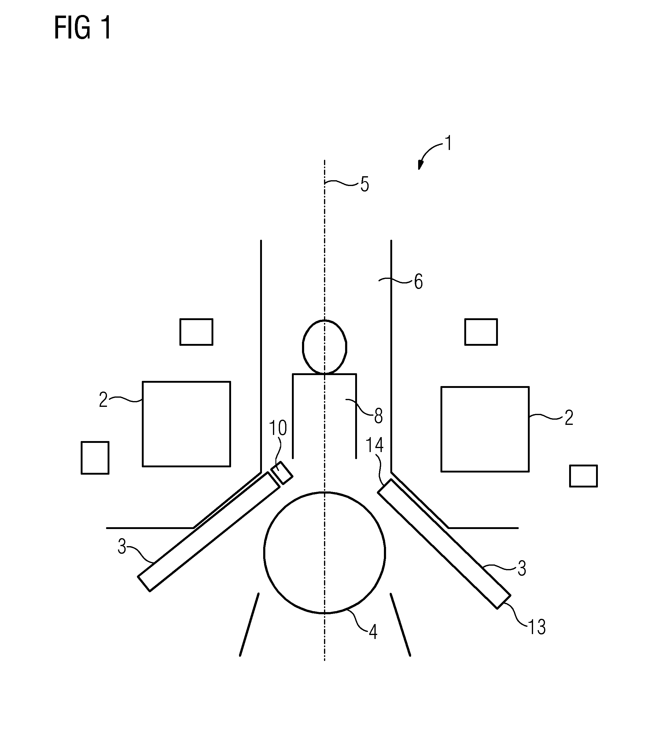
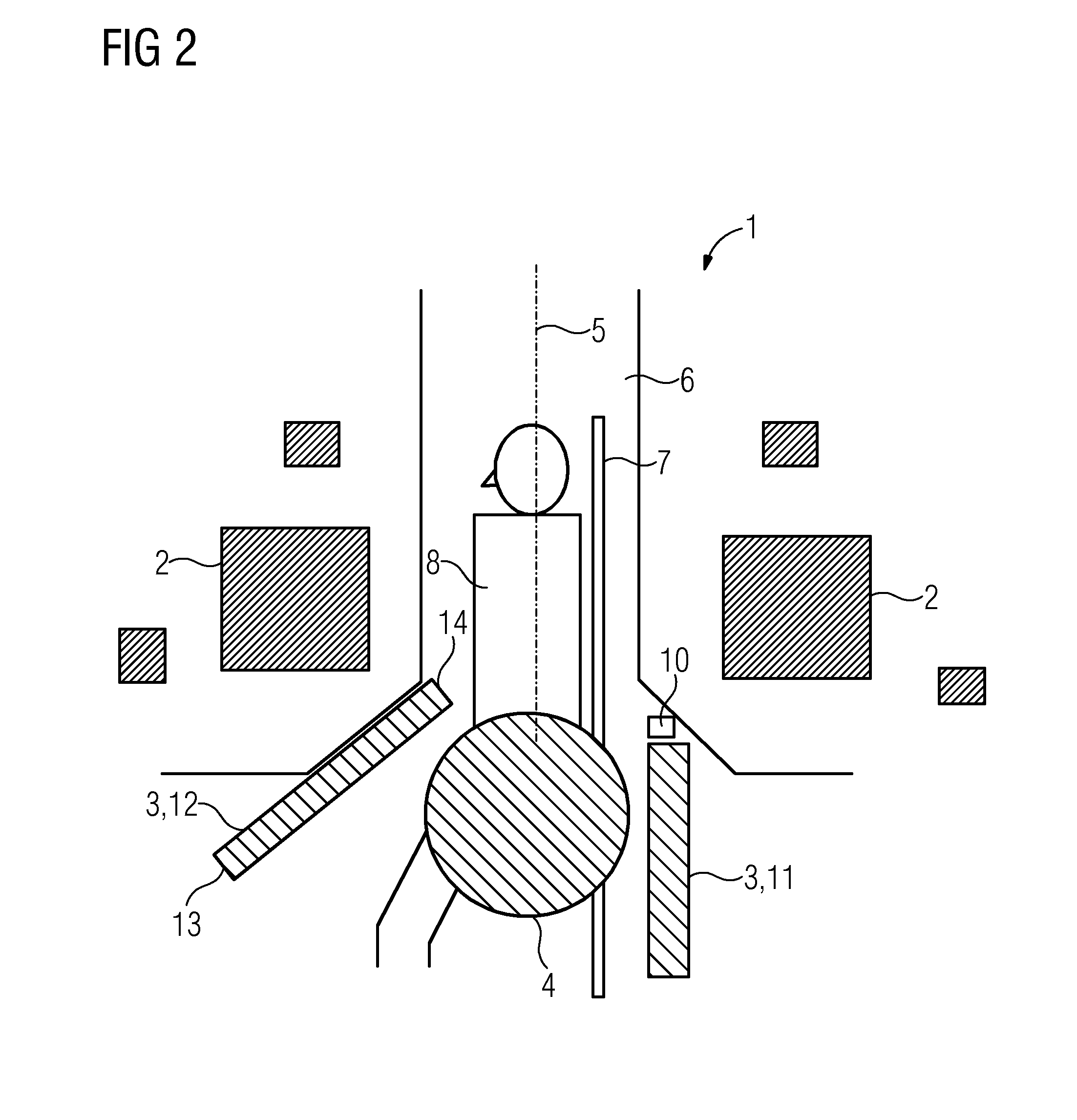
[0030]FIG. 1 shows a plan view of a magnetic resonance device 1. The magnetic resonance device 1 has a main field magnet 2, which is provided to generate a magnet volume. The magnet volume has an imaging region 4, in which the body region of a patient 8 to be examined by the magnetic resonance device 1 is positioned. The main field magnet 2 has a number of magnetic field-generating elements, which are arranged in the manner of a hollow cylinder around the patient 8. This results in a tunnel-type opening 6 having a longitudinal axis 5. The magnetic resonance device 1 also has at least one gradient coil 3 in a spatially opening configuration.

[0031]The magnetic field-generating elements of the main field magnet 2 are arranged in such a manner that the imaging region 4 of the magnet volume is displaced along the longitudinal axis 5 defined by the main field magnet 2 to one end of the tunnel-type opening 6. Part of the imaging region 4 of the magnet volume is located outside the tunnel-t...

second embodiment

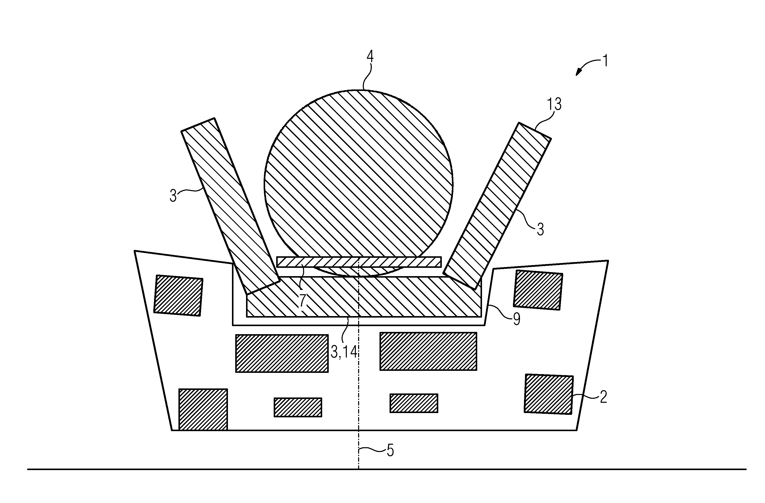
[0036]FIG. 3 shows a longitudinal section through an alternative second embodiment of the magnetic resonance device 1. All of the main field magnet 2 is arranged below the patient support apparatus 7. The main field magnet 2 therefore does not restrict accessibility to the body region of the patient 8 being examined from above or from the side.

[0037]In this exemplary embodiment, the body region of the patient 8 being examined is positioned directly above the center of the main field magnet 2. The patient 8 is positioned essentially radially to a longitudinal axis 5 defined by the main field magnet 2. However, the patient 8 can also be positioned differently. In particular, a magnetic resonance device 1 shown in this exemplary embodiment can examine any body part of a patient 8, providing the patient 8 with more free space than conventional magnetic resonance devices.

[0038]In the instance shown, the gradient coil 3 is configured in the manner of a dish, the base of the dish being let...


PUM


Abstract

A magnetic resonance device with at least one main field magnet and at least one gradient coil is provided. The magnetic resonance device provides more free space for the patient and treatment providers; the magnetic resonance device has at least one main field magnet, which is provided to generate a magnet volume. The magnet volume has an imaging region, which is displaced from the center of the main field magnet along a longitudinal axis defined by the main field magnet. The magnetic resonance device also has a gradient coil. In the direction of the longitudinal axis defined by the main field magnet, the gradient coil has a first side facing away from the main field magnet and a second side facing the main field magnet. The gradient coil has a cross-section with a larger area on the first side facing away than on the second facing side. The gradient coil is provided to generate variable magnetic gradient fields, the gradient fields being provided for magnetic resonance imaging in the imaging region of the magnet volume.

Description

CROSS-REFERENCE TO RELATED APPLICATIONS[0001]This application claims priority to DE Application No. 102013214880.1, having a filing date of Jul. 30, 2013, the entire contents of which are hereby incorporated by reference.FIELD OF TECHNOLOGY[0002]The following relates to a magnetic resonance device with at least one main field magnet and gradient coil.BACKGROUND[0003]Magnetic resonance devices are used to generate sectional images of the body of a patient which provide a treatment provider with information about the current anatomical and / or physiological state of the patient.[0004]Standard magnetic resonance devices contain at least one main field magnet, which generates a magnet volume that has an imaging region that is suitable for magnetic resonance imaging. Magnetic resonance devices also contain at least one gradient coil, which generate variable magnetic gradient fields, which are required for the spatial encoding of the magnetic resonance signal.[0005]The imaging region of th...

Claims


Application Information

Patent Timeline
Patent Type & Authority Applications(United States)
IPC IPC(8): G01R33/385A61B5/055G01R33/48
CPCG01R33/385A61B5/0555G01R33/48G01R33/3806G01R33/3808A61B5/4343A61B5/004A61B5/055A61B5/704
Inventor BLASCHE, MATHIASFEIWEIER, THORSTENGEBHARDT, MATTHIASKRUIP, MARCELWICKLOW, KARSTEN
Owner SIEMENS AG
Learn More