Mechanical press system and method of removing salt using the same

a mechanical press and salt technology, applied in the field of systems and methods for removing salts, can solve the problems of increasing the risk of accidental release of such materials

Inactive Publication Date: 2015-02-12
GE HITACHI NUCLEAR ENERGY AMERICAS
View PDF2 Cites 2 Cited by
  • Summary
  • Abstract
  • Description
  • Claims
  • Application Information

AI Technical Summary

Problems solved by technology

However, the relatively high temperatures will also vaporize volatile contaminants and radioactive materials within the mixture, which requires re

Method used


Image

  • Mechanical press system and method of removing salt using the same
  • Mechanical press system and method of removing salt using the same
  • Mechanical press system and method of removing salt using the same

Examples


Embodiment Construction

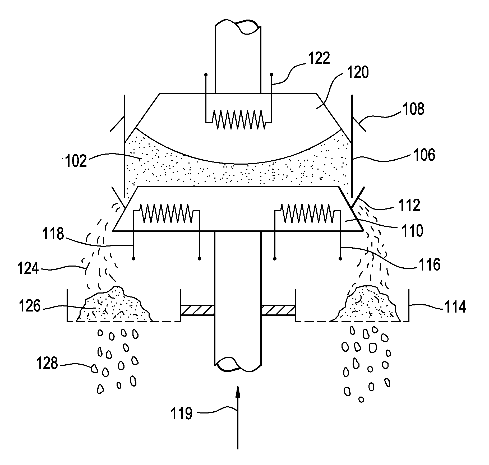
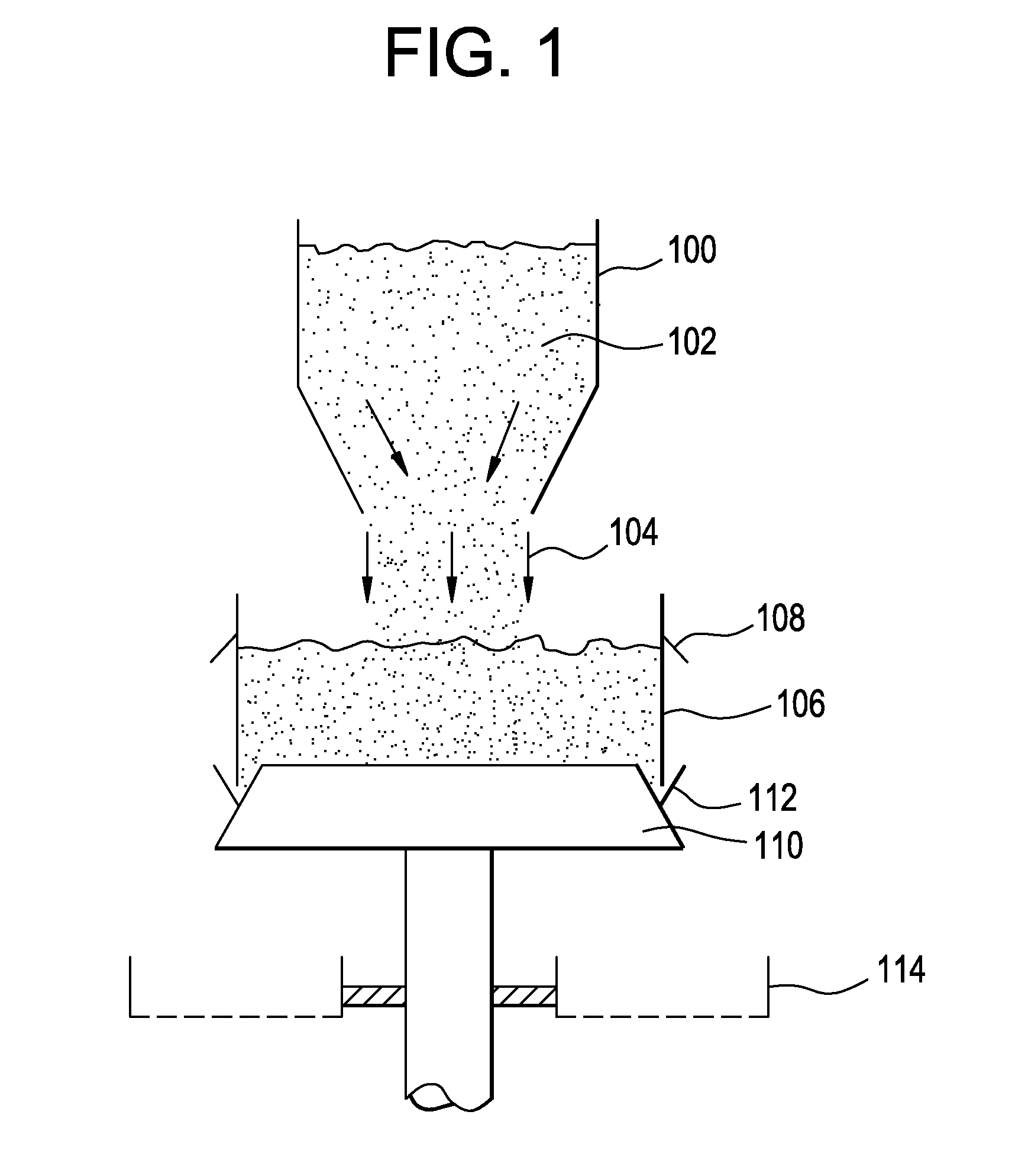
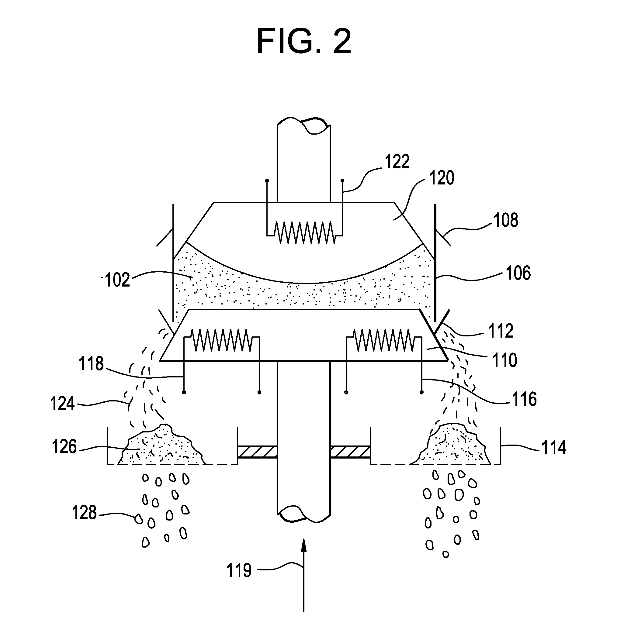
[0006]A mechanical press system may include an upper press body including a curved bottom portion and an upper lip portion surrounding the curved bottom portion; a first heater within the upper press body; a lower press body aligned below the upper press body, the lower press body including a top portion and a lower lip portion surrounding the top portion, the upper press body and lower press body configured to come together during a compression state and configured to move apart during a decompression state; a second heater within the lower press body; and a containment band configured to rest on the lower lip portion of the lower press body and to surround the upper lip portion of the upper press body during the compression state and configured to separate from the upper press body and the lower press body during the decompression state.

[0007]A method of removing salt from a dendritic mixture may include loading the dendritic mixture into a mechanical press system, the dendritic m...


PUM

PropertyMeasurementUnit
Temperatureaaaaaaaaaa
Shapeaaaaaaaaaa
Metallic bondaaaaaaaaaa

Abstract

A method of removing salt from a dendritic mixture includes loading the dendritic mixture into a mechanical press system. The dendritic mixture includes a metallic dendrite and salt dispersed within the metallic dendrite. The dendritic mixture is heated to liquefy the salt without volatilizing one or more metals of the metallic dendrite. The dendritic mixture is also compressed to obtain a fluidic mixture and an ingot of the metallic dendrite. The fluidic mixture may include molten salt and residual metallic dendrite. The fluidic mixture may be filtered to separate the residual metallic dendrite from the molten salt.

Description

BACKGROUND[0001]1. Field[0002]The present disclosure relates to systems and methods for removing salts from electrolytically-reduced metals.[0003]2. Description of Related Art[0004]During a fuel fabrication process, metal oxides may be obtained from spent nuclear material and electrolytically reduced to their metallic form. The resulting metal from the electrolytic reduction step may be in the form of a dendritic structure (e.g., cake), which resembles a porous metal sponge with a relatively high surface area. As a result, the dendritic structure will also have a relatively large amount of salt adhered to and included therein from the electrolytic reduction step.[0005]To remove the salt from the dendritic structure, a cathode processor is conventionally used to subject the mixture to relatively high temperatures to vaporize the salt. However, the relatively high temperatures will also vaporize volatile contaminants and radioactive materials within the mixture, which requires relativ...

Claims


Application Information

Patent Timeline
IPC IPC(8): C22B7/00
CPCC22B7/005G21F9/28G21F9/34G21F9/36B30B13/00B30B15/064
Inventor KOSSLOW, ZACHARY WILLIAM
Owner GE HITACHI NUCLEAR ENERGY AMERICAS
Why Eureka
Try Eureka