
Voltage regulator with switching and low dropout modes

a voltage regulator and low dropout technology, applied in the direction of electric variable regulation, process and machine control, instruments, etc., can solve the problems of power consumption, less effective noise-sensitive devices such as radios, and reduced battery capacity

Active Publication Date: 2015-02-12
MICROSEMI CORP
View PDF22 Cites 42 Cited by
  • Summary
  • Abstract
  • Description
  • Claims
  • Application Information

AI Technical Summary

Benefits of technology

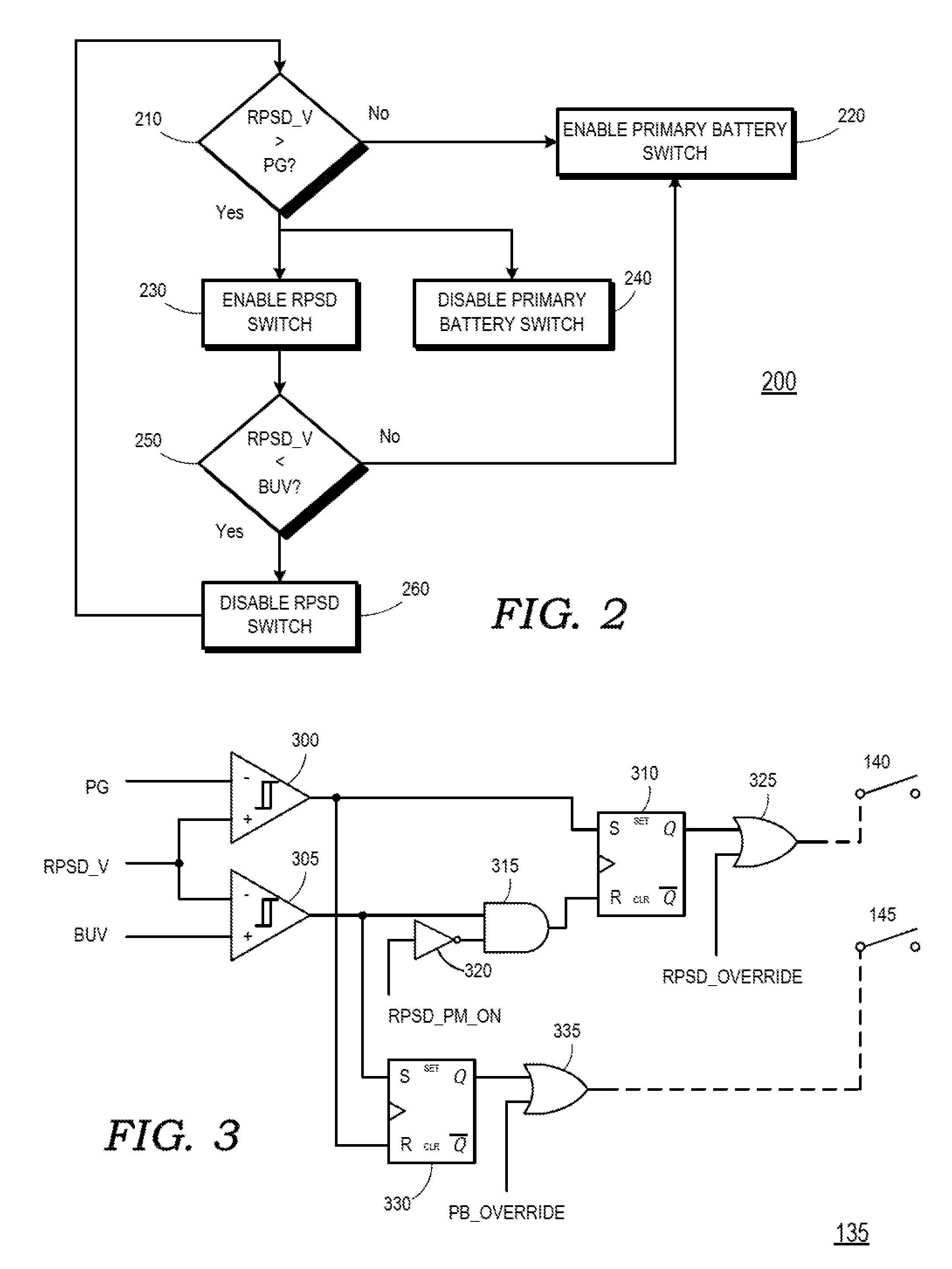
The present patent is about a power control system for electronic devices, particularly wireless sensors, that use different types of voltage regulators to provide power. The technical effects of the patent include improved noise reduction, efficiency, and battery capacity. The patent describes a system that selectively controls the voltage regulator based on the input and output voltages, and can switch between a switching mode and a low dropout mode depending on the needs of the electronic device. The system also includes a power control logic that selects between a rechargeable power storage device and a primary battery for powering the sensor and radio, and a circuit diagram of the power control system.

Problems solved by technology

Due to the periodic nature of the switching, the output voltage has an inherent ripple, making it less effective for noise sensitive devices, such as radios, especially during a receive mode of the radio.
Power consumption is another tradeoff associated with voltage regulators.
Some electronic devices are powered by batteries, so a low efficiency voltage regulator will result in a reduced battery capacity.
An LDO regulator may have improved noise characteristics, but lower efficiency than a switching regulator, resulting in increased current draw from the battery and lower battery capacity.

Method used


Image

  • Voltage regulator with switching and low dropout modes
  • Voltage regulator with switching and low dropout modes
  • Voltage regulator with switching and low dropout modes

Examples


Embodiment Construction

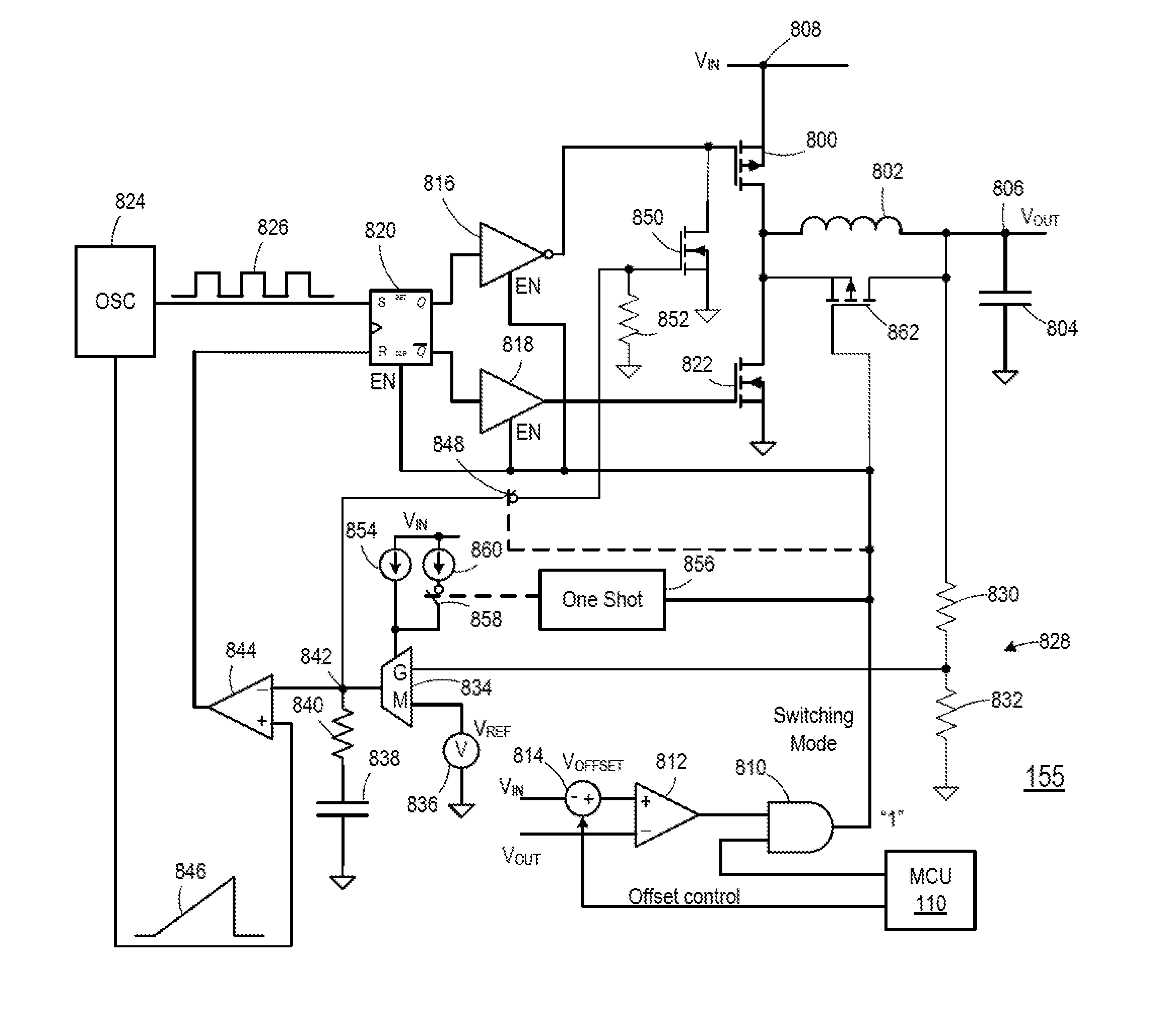
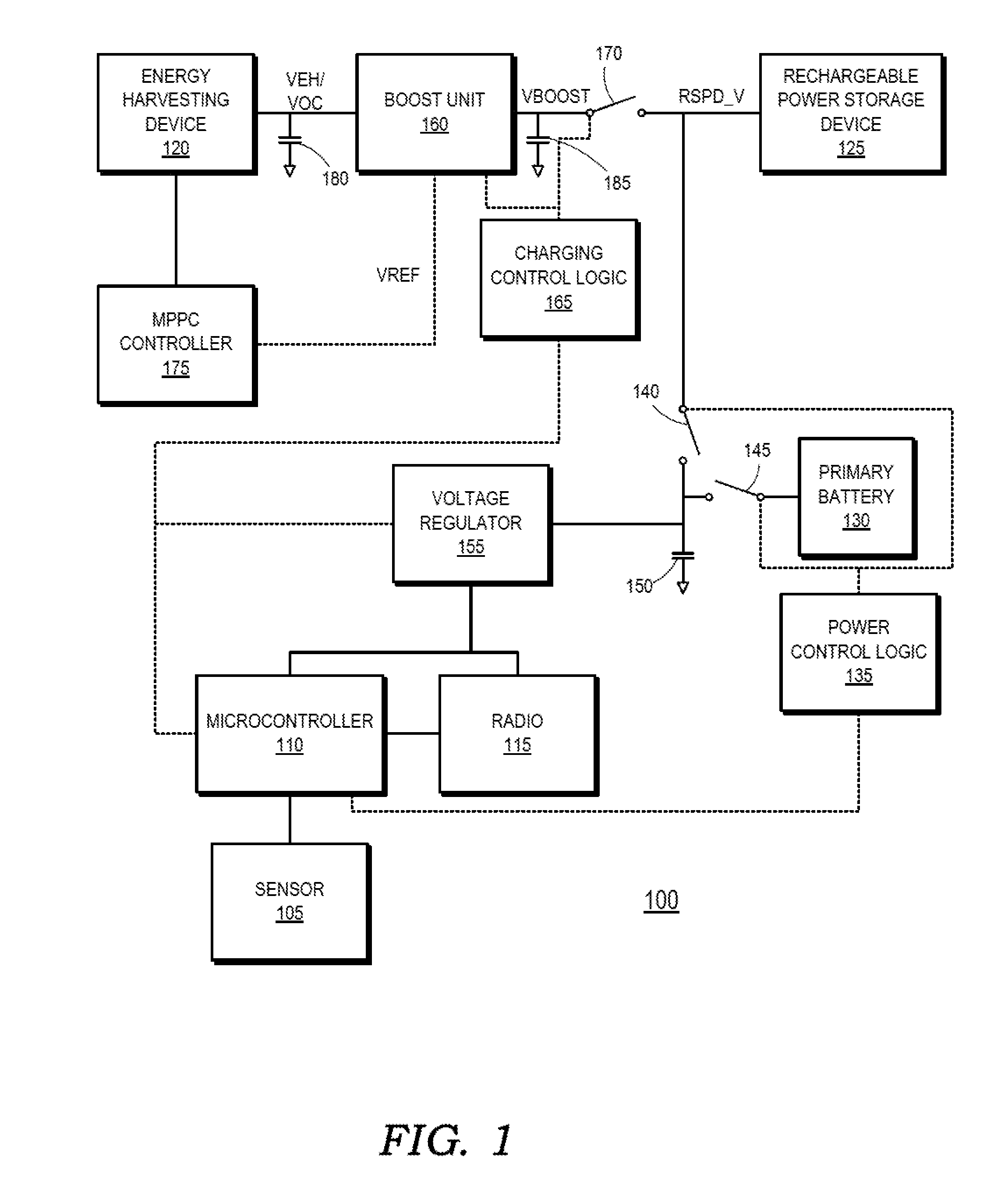
[0019]FIGS. 1-8 illustrate example circuits and techniques for powering a wireless sensor module using an energy harvesting device, a rechargeable power storage device, and a primary battery. The primary battery may be a non-rechargeable battery, such as a chemical battery, that provides power to the rechargeable power storage device during periods of low output by the energy harvesting device, which results in the draining of the rechargeable power storage device. The selected power source is provided to a voltage regulator to generate a supply voltage for powering at least a radio in the wireless sensor module. The voltage regulator may be selectively controlled to operate in a switching mode or a low dropout (LDO) mode depending on the operational state of the radio and / or the difference between the input and output voltages seen by the voltage regulator.

[0020]FIG. 1 is a simplified block diagram of a wireless sensor module 100. The wireless sensor module 100 includes a sensor 10...


PUM


Abstract

A voltage regulator includes an input terminal, an output terminal, a control circuitry, a buck mode switching converter, and a low dropout regulator circuit. The buck mode switching converter is arranged to convert a voltage signal received at the input terminal to a first voltage signal at the output terminal responsive to a first predetermined signal output from the control circuitry. The buck mode switching converter includes an electronically controlled switch in communication with an energy storage element. The low dropout regulator circuit is coupled between the input terminal and the output terminal and includes a linear circuit and is arranged to control a voltage drop across the linear circuit so as to provide a second voltage signal at the output terminal responsive to a second predetermined signal output from the control circuitry.

Description

CROSS REFERENCE TO RELATED APPLICATIONS[0001]This application claims priority to the U.S. Provisional Patent Application 61 / 864,200, filed on Aug. 9, 2013, the entirety of which is incorporated herein by reference.BACKGROUND[0002]1. Field of the Disclosure[0003]The present disclosure generally relates to powering electronic devices, and more particularly, to a voltage regulator with switching and low dropout modes.[0004]2. Description of the Related Art[0005]Voltage regulators are used to provide power supplies for electronic devices. Different types of voltage regulators exhibit different voltage stability, noise, and regulation efficiency characteristics. Switching voltage regulators, such as buck mode voltage regulators, periodically couple an input voltage source to an energy storage element to generate an output voltage. Due to the periodic nature of the switching, the output voltage has an inherent ripple, making it less effective for noise sensitive devices, such as radios, e...

Claims


Application Information

Patent Timeline
Patent Type & Authority Applications(United States)
IPC IPC(8): G05F1/575H02M3/156
CPCH02M3/156G05F1/575H02M3/1588Y02B70/10H02M1/0045
Inventor PEKER, ARKADIYDREXLER, BERNARDRESHEF, TAMIRRAJAN, REGHU
Owner MICROSEMI CORP
Learn More