
Determining the form of RF pulses for selective excitation in magnetic resonance imaging

Active Publication Date: 2015-02-12
SIEMENS HEALTHCARE GMBH +1
View PDF4 Cites 1 Cited by
  • Summary
  • Abstract
  • Description
  • Claims
  • Application Information

AI Technical Summary

Benefits of technology

This patent describes a new way to create pulses for magnetic resonance tomography that are selective and can be easily converted to a simplified description based on physical principles. This method is faster and more robust against interference effects than previous methods, and can be easily parallelized.

Problems solved by technology

The magnetic resonance methods according to the state of the art are very time-consuming and require extensive computational work.
Another drawback of the state of the art is that interference effects such as, for example, field inhomogeneity, have a major influence on the selective excitation and, instead of bringing about the desired selection, can result in a different selection.
In particular, a magnetic resonance method is to be put forward that requires the smallest possible time investment and the least possible computational work to generate selective excitations which are not sensitive to external interference effects.

Method used


Image

  • Determining the form of RF pulses for selective excitation in magnetic resonance imaging
  • Determining the form of RF pulses for selective excitation in magnetic resonance imaging
  • Determining the form of RF pulses for selective excitation in magnetic resonance imaging

Examples


Embodiment Construction

[0045]Other advantages, special features and practical refinements of the invention ensue from the presentation below of preferred embodiments making reference to the figures.

[0046]The figures show the following:

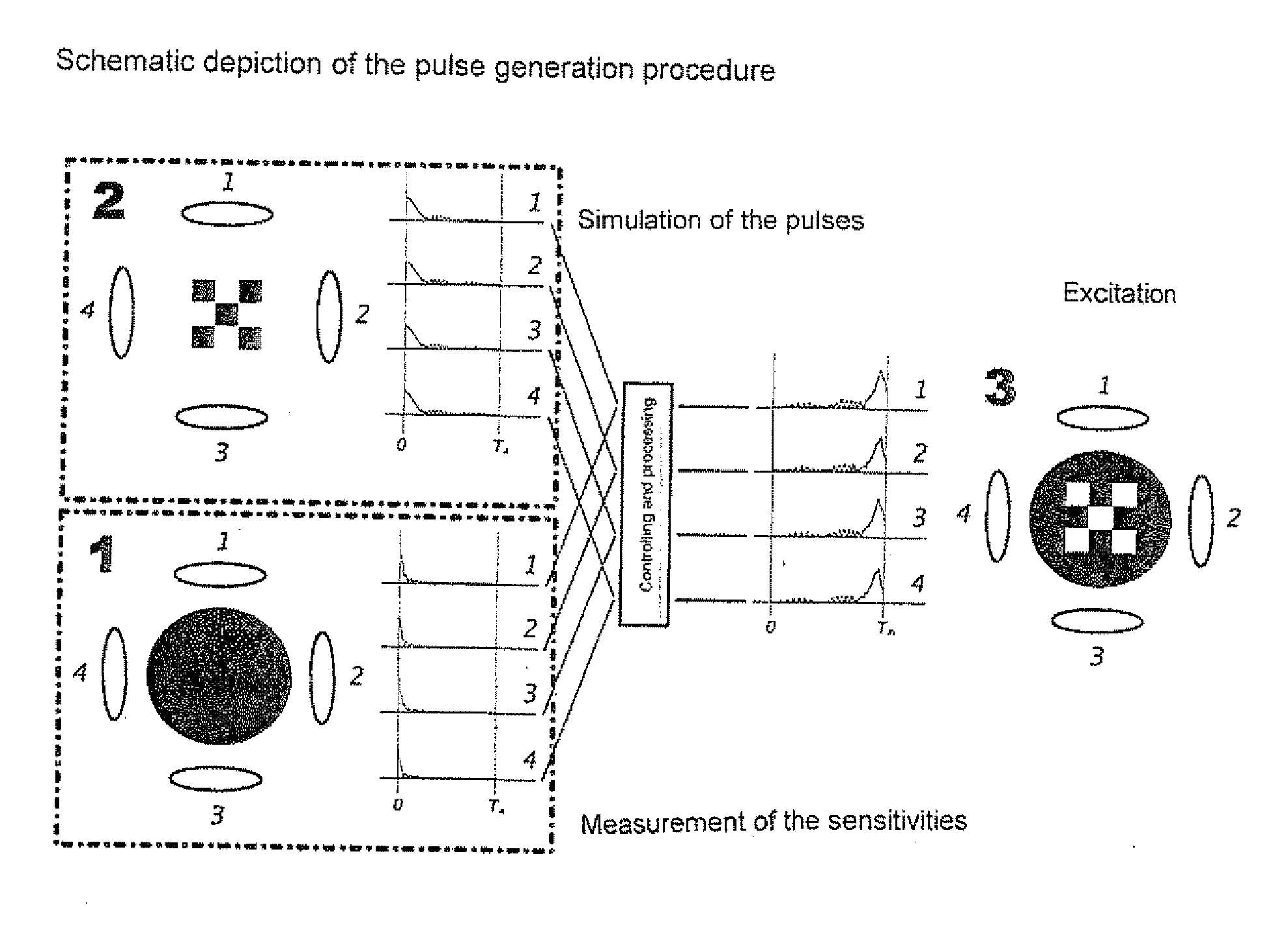
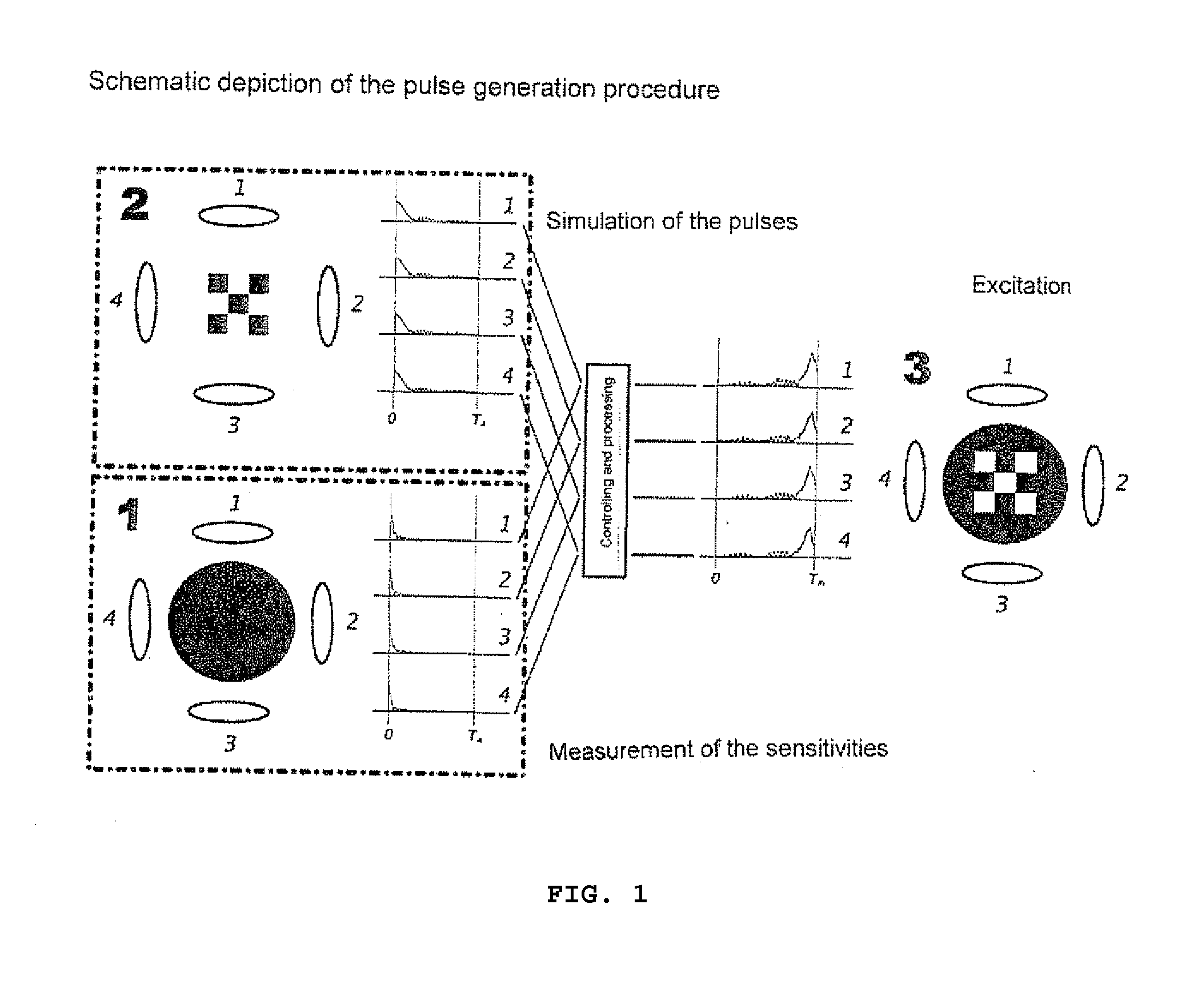
[0047]FIG. 1 a schematic depiction of the pulse generation procedure;

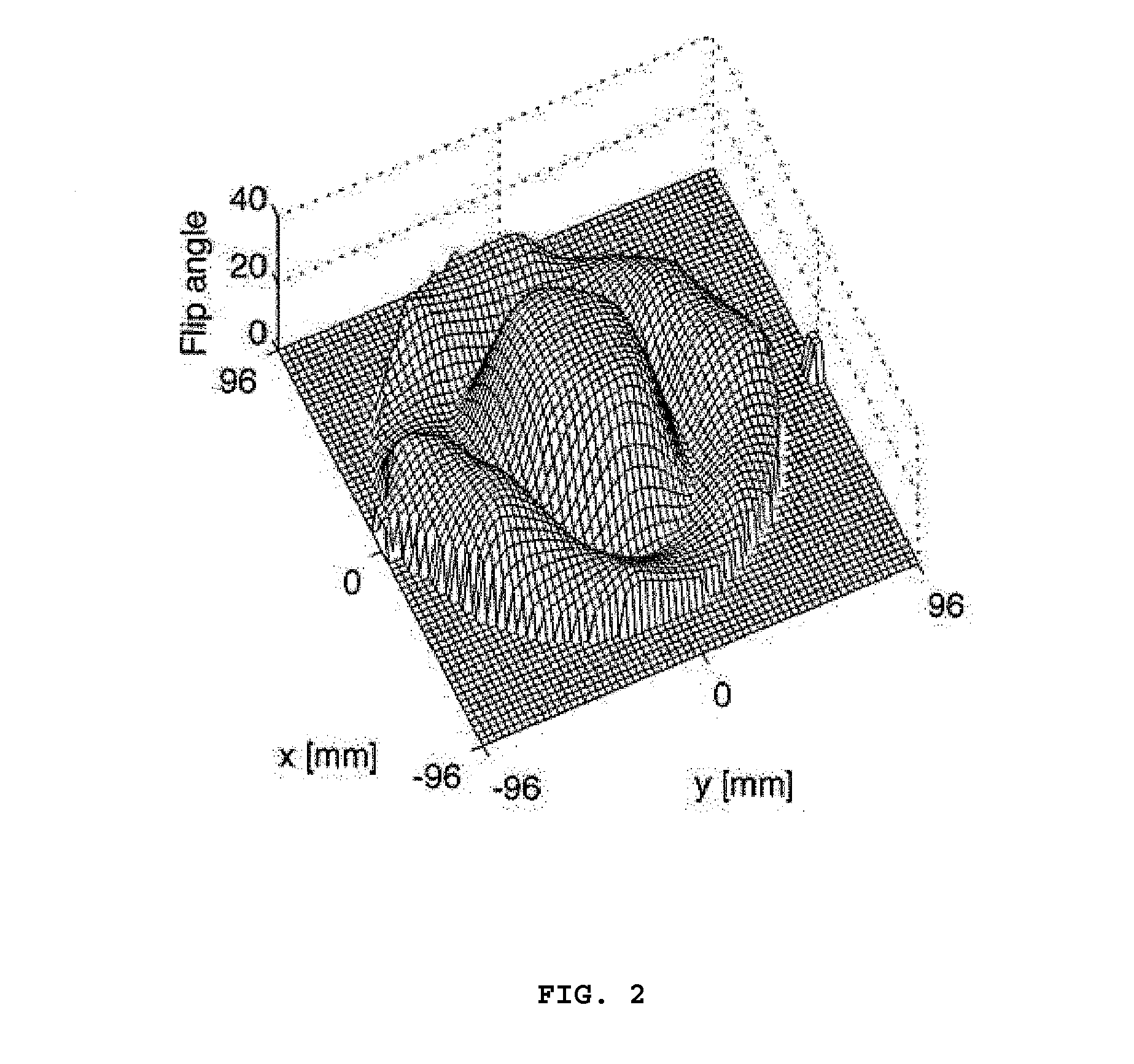
[0048]FIG. 2 a depiction of the spatial sensitivity of the coil and in another partial figure (upper right), the sensitivity to oscillations in another spatial plane (y-plane);

[0049]FIG. 3 a quantitative depiction of an excitation image, whereby a spatial distribution is shown in the x- and y-directions and in which the signal intensity is shown in the z-axis;

[0050]FIG. 4 an excitation pattern like in FIG. 3, but after the correction for inhomogeneities by means of a method according to the invention, and

[0051]FIG. 5 amplitudes and phases for generating the excitation profile according to FIG. 4.

[0052]The presented new method is used to determine selective high-frequency pulses for applications in magnetic ...


PUM


Abstract

The invention relates to a magnetic resonance method involving the generation of high-frequency pulses and magnetic gradients (gx, gy, gz) for the selective excitation of an object to be examined. According to the invention, the magnetic resonance method is characterized in that a magnetic resonance signal s(t) according to the following signal equation is generated:s(t)=∫Vm(rr,T)exp[t / T2]exp[tωs]exp[-kr(T-t)·rr]3rwherein m(lr,t) stands for a desired transversal magnetization after the selective excitation, t stands for a time, {right arrow over (r)} stands for a position vector and T stands for a duration of a pulse, and whereby s(t) stands for a magnetic resonance signal, V stands for a volume that is to be examined, T2 stands for a transversal relaxation time, and ωs stands for a shift of the resonance frequency. The invention also relates to a nuclear spin tomograph for carrying out the magnetic resonance method.

Description

FIELD OF THE INVENTION[0001]The invention relates to a magnetic resonance method involving the generation of high-frequency pulses and magnetic gradients (Gx, Gy, Gz) for spatially selective excitation.[0002]It is known that magnetic resonance excitations can be generated by combinations of high-frequency signals with magnetic gradients (especially gradient pulses).[0003]Such magnetic resonance methods can be used for imaging and / or for spectroscopy.[0004]The invention also relates to a nuclear spin tomograph having a means for generating magnetic gradients, a means for generating high-frequency pulses, a means for data acquisition, and a means for generating a static main magnetic field.STATE OF THE ART[0005]The fundamental principles of spatially resolved nuclear magnetic resonance—which is taken below as the basis for the understanding of the invention—are described, for example, in the monograph by P. Mansfield and P. G. Morris titled “MMR Imaging in Biomedicine” (Academic Press...

Claims


Application Information

Patent Timeline
IPC IPC(8): G01R33/483G01R33/56G01R33/48G01R33/385
CPCG01R33/4833G01R33/4818G01R33/56G01R33/385
Inventor GUMBRECHT, RENEVAHEDIPOUR, KAVEHSTOECKER, TONYSHAH, NADIM JONI
Owner SIEMENS HEALTHCARE GMBH
Learn More