
Device and method for autonomously performing an implicit detach operation

a technology of implicit detachment and device, applied in the field of wireless communication, can solve the problems of detach signalling having limited usefulness, potential signalling overload, signalling overload, etc., and achieve the effect of reducing the amount of signalling and reducing the requirement of signalling capacity

Active Publication Date: 2015-02-12
NEC CORP
View PDF3 Cites 5 Cited by
  • Summary
  • Abstract
  • Description
  • Claims
  • Application Information

AI Technical Summary

Benefits of technology

The present invention helps reduce the amount of communication needed in a wireless system and reduces the capacity requirement for detach operations.

Problems solved by technology

With machine-type communications, signalling overload is expected to become a significant issue for networks as networks will face more and more connected devices due at least in part to the introduction of Machine Type Communications devices and this will result in potential signalling overload, simply due to the increased number of devices that can be attached to the network at any time.
While both the above mechanisms seem viable solutions, it should now be appreciated that in the following situations detach signalling has limited usefulness:
a) a situation in which the device attaches so that it can transmit a data transmission that is smaller than an average transmission by devices in the system;
b) a situation in which multiple devices are allocated or assigned (e.g. by the network) different communication windows, and at the end of its communication window each device will not communicate any longer with the network until the next-occurring communication window;
c) a situation in which the device is assigned or allocated a grant time interval, and at the end of the grant time interval the device will not communicate any longer with the network until the next grant time interval.
This flag can potentially give a limited possibility for the network to reduce signalling load due to devices detaching.

Method used


Image

  • Device and method for autonomously performing an implicit detach operation
  • Device and method for autonomously performing an implicit detach operation
  • Device and method for autonomously performing an implicit detach operation

Examples


Embodiment Construction

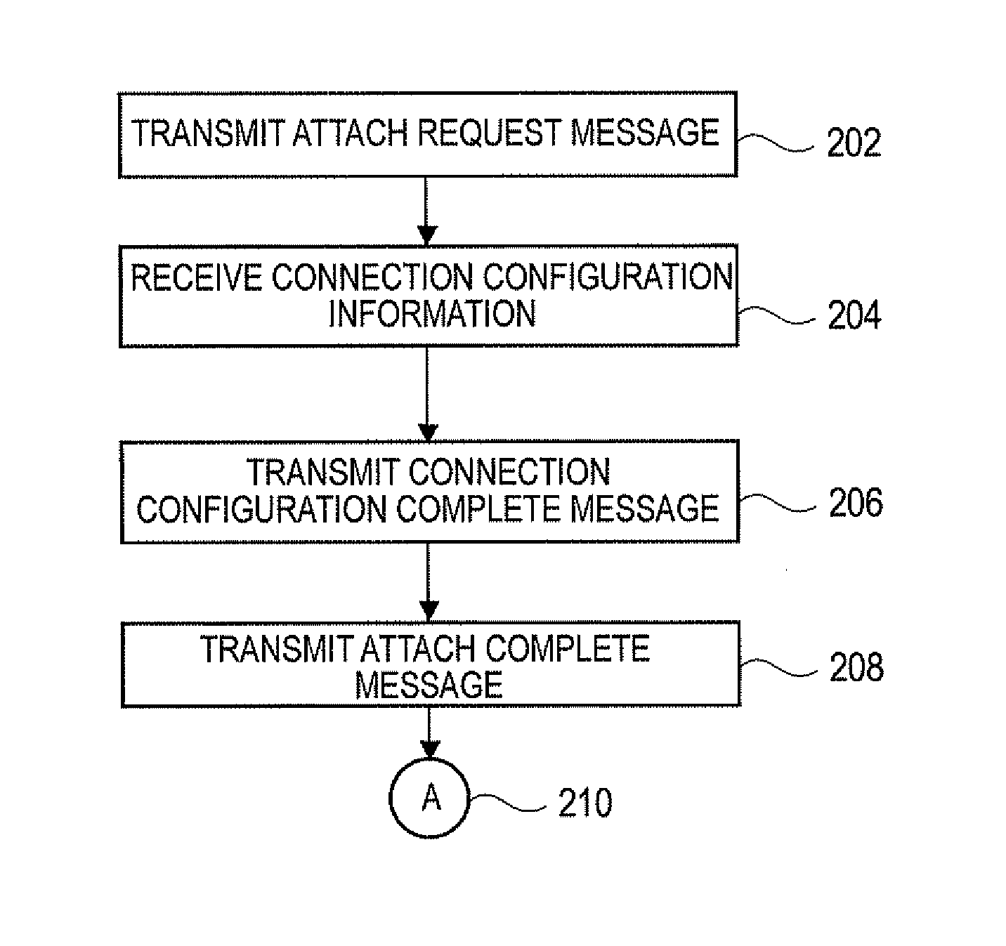
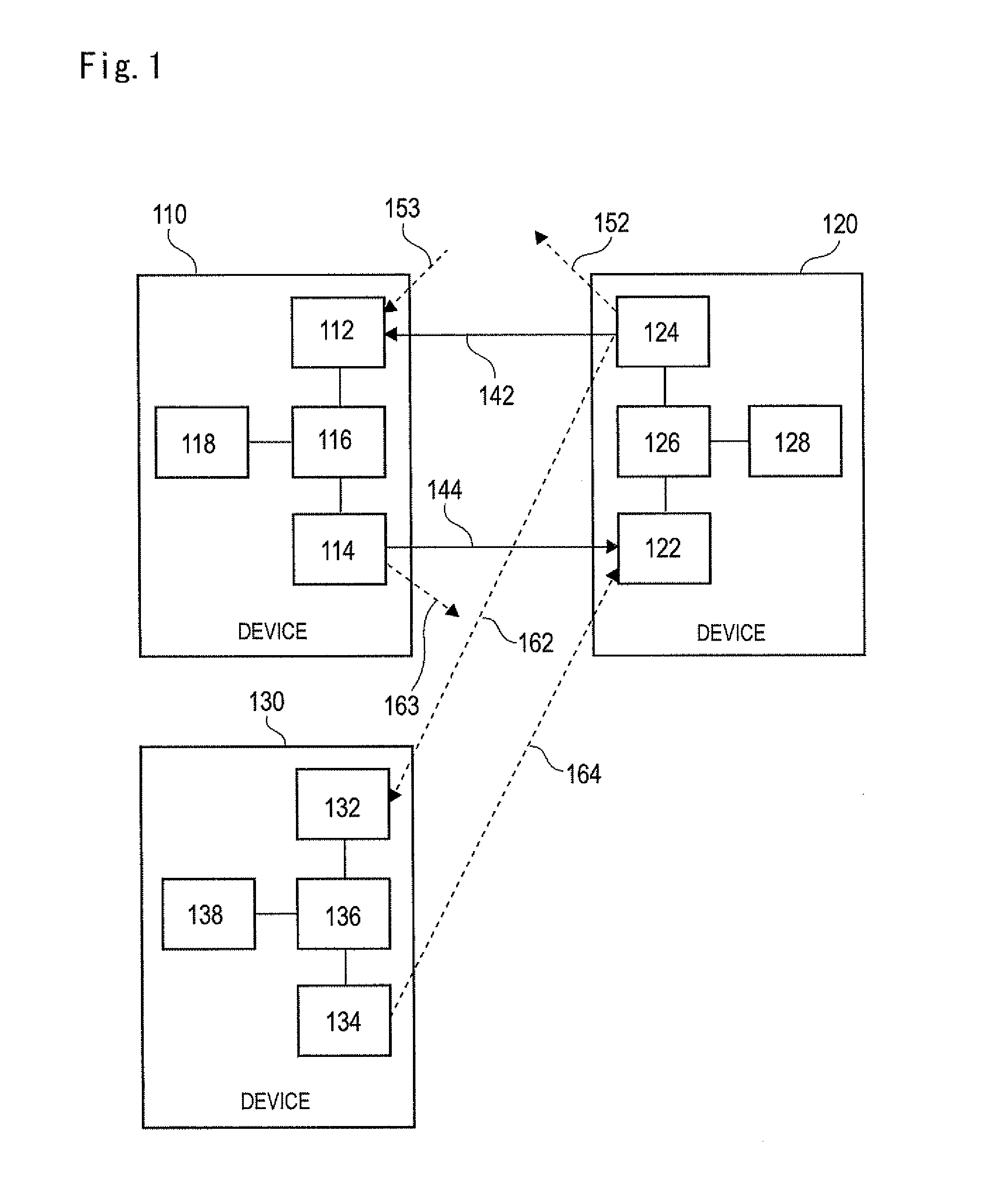
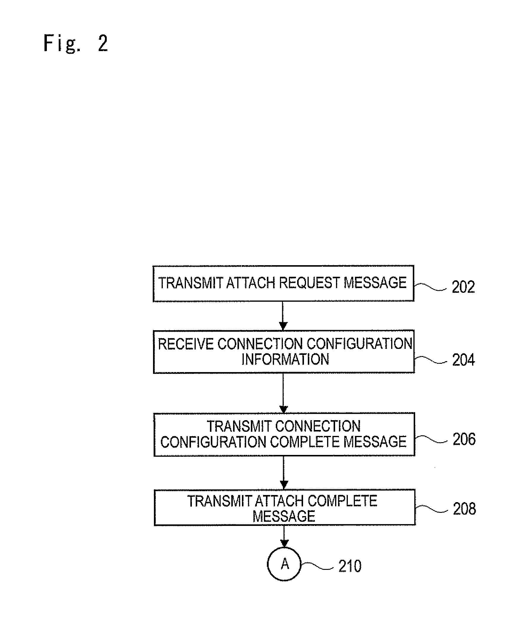
[0072]It should be understood that FIGS. 1 to 5 apply both to a known wireless communication system and also to aspects of the present invention described herein and are used to describe operation according to a known wireless communication system and also to describe operation of a device employing one or more of the inventive features described herein. Further, it should be understood that FIGS. 6 to 9 apply to embodiments and aspects of the present invention described herein.

[0073]The term ‘wireless communication device’ herein means a device arranged to communicate wirelessly with another device that is also arranged to communicate wirelessly. The term ‘wireless communication device’ encompasses, but is not limited to, a wireless terminal of a wireless cellular communication system comprising at least one base station and at least one, typically plural, wireless terminals.

[0074]In FIG. 1, a wireless communication device 110 comprises a receiver 112, a transmitter 114, a processo...


PUM


Abstract

A device can communicate wirelessly with another device in a wireless communication system and is arranged to receive configuring information defining a detach configuration. By using the detach configuration, the device can autonomously perform an implicit detach operation thus terminating a communication link between the device and the other device. Optionally, when the detach configuration includes an explicit detach mode, the device transmits an indicating signal indicating the detach operation. The indicating signal transmitted by the device may comprise a DETACH REQUEST message. Preferably the device can store the configuring information and can store program information, and can perform the detach operation by using the stored program information and the stored configuring information.

Description

TECHNICAL FIELD[0001]The present patent application relates to wireless communication between devices, and to signalling associated with one or more wireless communication devices performing a detach operation whereby a wireless communication link is terminated. Aspects of the present invention will be described which allow the amount of such signalling associated with a detach operation to be reduced.BACKGROUND ART[0002]In the context of work performed by the Third Generation Partnership Project (3GPP) on System Improvements for Machine-Type Communications (SIMTC), 3GPP have introduced a feature called “time controlled” which addresses devices that can send or receive data only at certain defined time periods and potentially only need a very small time duration or interval to communicate with the network. The following is stated in Technical Report document 3GPP TR 23.888 v1.6.0, sub clause 5.9.1:“Typically, an MTC User agrees with an operator on a predefined time period for a grou...

Claims


Application Information

Patent Timeline
Patent Type & Authority Applications(United States)
IPC IPC(8): H04W60/06H04W4/50H04W4/70
CPCH04W60/06H04W8/18H04W4/50H04W4/70
Inventor IANEV, ISKRENLAIR, YANNICK
Owner NEC CORP
Learn More