Ultrasound probe

a technology of ultrasonic probes and probes, applied in mechanical vibration separation, medical science, diagnostics, etc., can solve the problems of inability to obtain longitudinal vibration of target thickness

Inactive Publication Date: 2015-02-12
KONICA MINOLTA INC
View PDF4 Cites 8 Cited by
  • Summary
  • Abstract
  • Description
  • Claims
  • Application Information

AI Technical Summary

Benefits of technology

The ultrasound probe described in this patent has a design that allows for reliable and efficient connections between the piezoelectric bodies and the control electrode, even if there are variations in the manufacturing process. This design also allows for precise control of the aperture of the piezoelectric bodies.

Problems solved by technology

However, if a width W of the piezoelectric body is equal to or greater than a predetermined value with respect to the thickness T, in some cases a thickness longitudinal vibration and a width vibration that depends on the width W interfere with each other, and a target thickness longitudinal vibration cannot be obtained.
On the other hand, if the width W of the piezoelectric body is less than a predetermined value with respect to the thickness T, the piezoelectric body may be too thin and complex vibration modes will interfere with each other, and a target thickness longitudinal vibration cannot be obtained.

Method used


Image

  • Ultrasound probe
  • Ultrasound probe
  • Ultrasound probe

Examples


embodiment 1

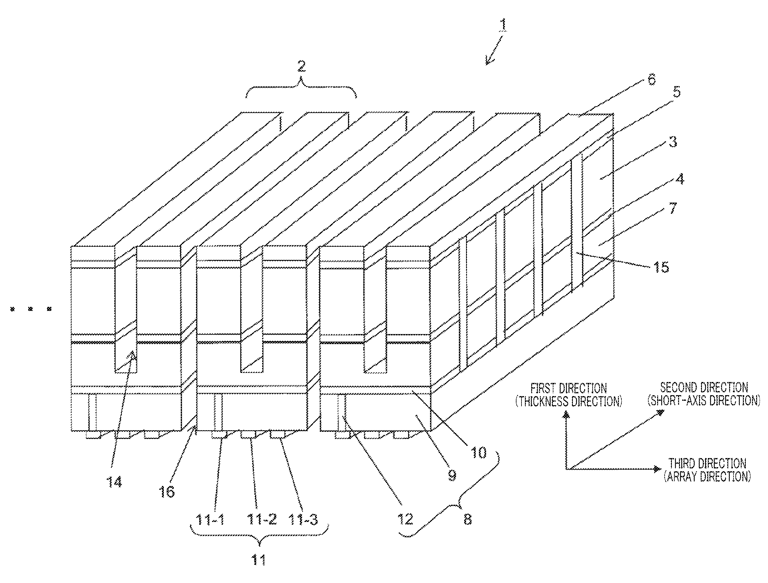
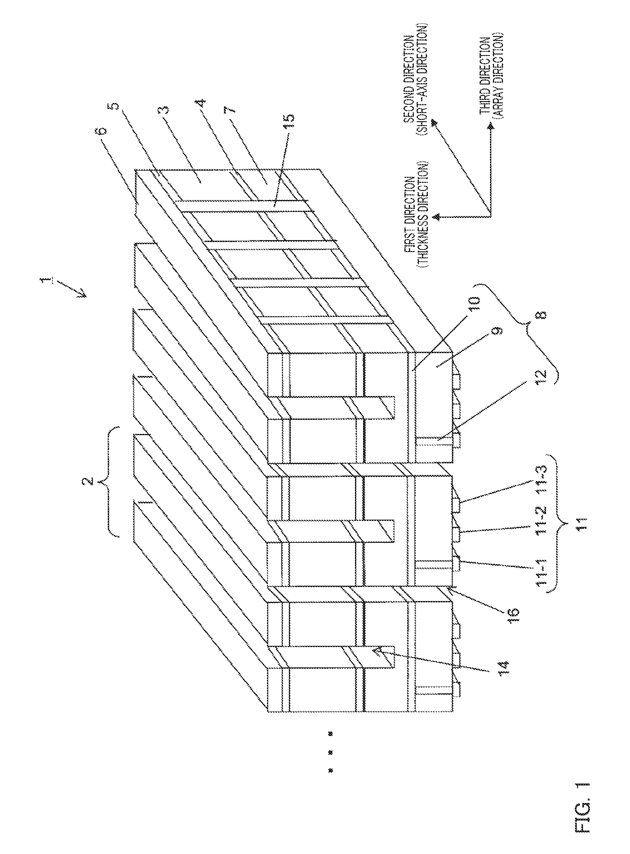
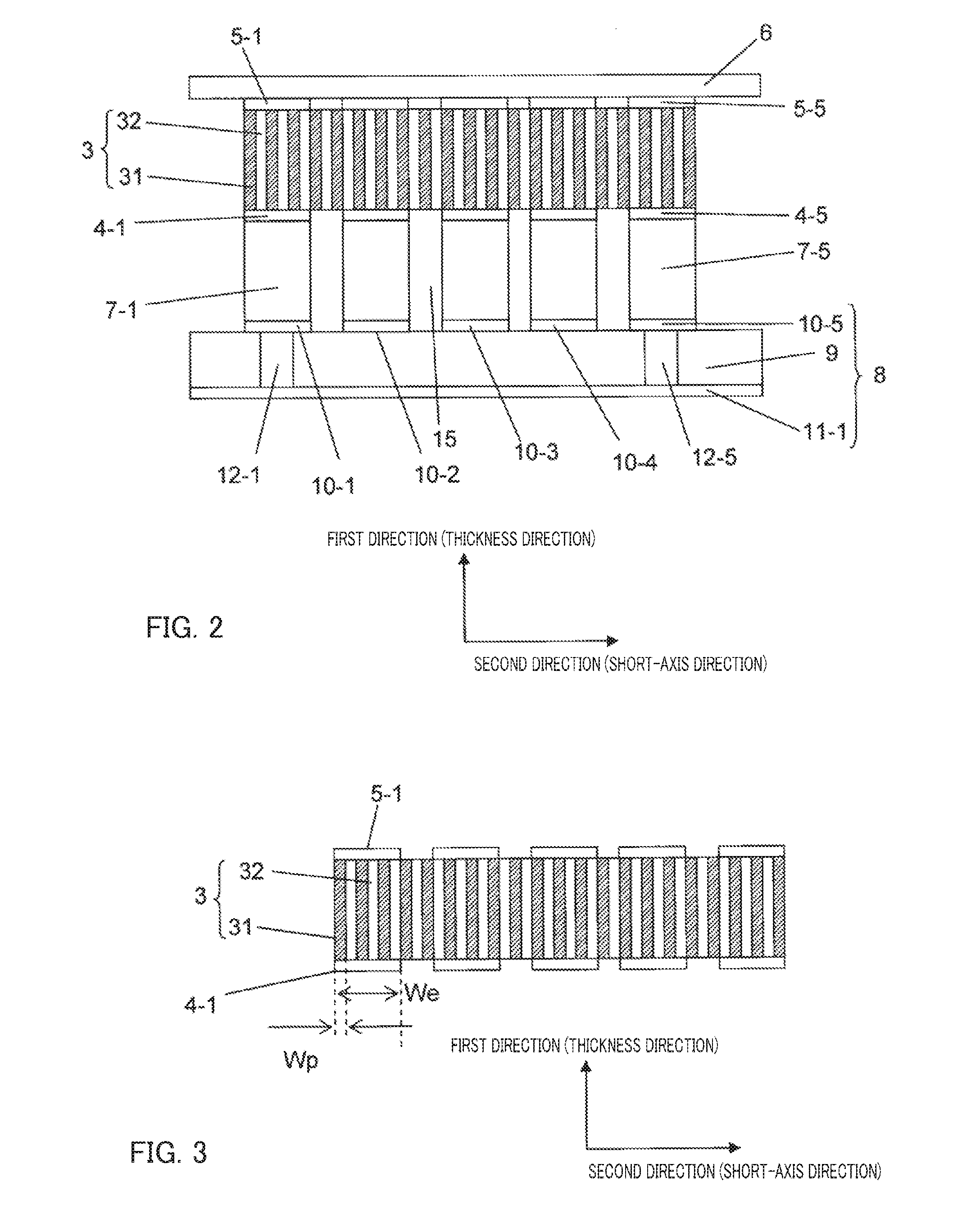
[0051]FIG. 1 is a perspective view that illustrates an ultrasound probe according to Embodiment 1 of the present invention. Ultrasound probe 1 shown in FIG. 1 is used in contact with a subject such as a living body. Ultrasound probe 1 is a transducer that directs ultrasound to the subject by applying an electrical signal to piezoelectric body 3 inside ultrasound probe 1, and converts ultrasound reflected from inside subject into an electrical signal using piezoelectric body 3. As shown in FIG. 1, ultrasound probe 1 includes piezoelectric body 3, second electrode 4, first electrode 5, ground layer 6, intermediate layer 7, double-sided FPC 8, third electrode 11, first groove 14, second groove 15, third groove 16, a back surface material (not shown), a plurality of matching layers (not shown), and a lens (not shown).

[0052]When a voltage generated by a transmitting circuit (not shown) inside the ultrasound diagnosis apparatus or ultrasound probe 1 is applied between first electrode (gro...

embodiment 2

[0116]FIG. 23 is a perspective view illustrating an ultrasound probe according to Embodiment 2 of the present invention. Ultrasound probe 111 of Embodiment 2 includes single-sided FPC 13 instead of double-sided FPC 8 that is included in ultrasound probe 1 of Embodiment 1. Other than this difference, ultrasound probe 111 is the same as ultrasound probe 1 of Embodiment 1, and components in FIG. 23 that are common with FIG. 1 are denoted by the same reference numerals as in FIG. 1.

[0117]Single-sided FPC 13 includes third electrode 11 that extends in the second direction (short-axis direction) and insulating layer 9. Insulating layer 9 is formed of a polyimide film, polyester film or the like. Similarly to double-sided FPC 8, single-sided FPC 13 is a commercially available component on which third electrode 11 and insulating layer 9 are laminated in advance, and use of the commercially available component is the most convenient way to obtain single-sided FPC 13.

[0118]Insulating layers 1...

embodiment 3

[0127]FIG. 31 is a perspective view illustrating an ultrasound probe according to Embodiment 3 of the present invention. While insulating layers 19 are provided on parts of third electrodes 11 in ultrasound probe 111 of Embodiment 2, according to the present embodiment insulating layers 29 are provided on intermediate layers 7 in the second direction (short-axis direction) as shown in FIG. 31. Other than this difference, the present embodiment is the same as Embodiment 2, and components in FIG. 31 that are common with FIG. 23 are denoted by the same reference numerals as in FIG. 23.

[0128]In a case where intermediate layer 7 is formed from a metallic material such as aluminum, insulating layer 29 is formed by selective anodizing. Further, in a case where intermediate layer 7 is formed from an insulating material, as shown in FIG. 6 and FIG. 7, by selectively forming the conductive layers, intermediate layer 7 at a portion at which a conductive layer is not provided may be used as ins...


PUM


Abstract

An ultrasound probe includes a laminated body having: a piezoelectric body having a thickness in a first direction; a first electrode and a second electrode that face each other so as to sandwich the piezoelectric body in the first direction; an intermediate layer that is electrically connected with the second electrode and that is provided on an opposite side to the piezoelectric body with respect to the second electrode; and a third electrode that extends in a second direction that is orthogonal to the first direction. A plurality of the first electrodes and second electrodes are arranged at predetermined intervals in the second direction. A plurality of the laminated bodies are arranged in a third direction. A first groove that penetrates through the first electrode, the piezoelectric body, and the second electrode and a part of the intermediate layer is formed in the laminated body.

Description

BACKGROUND OF THE INVENTION[0001]1. Field of the Invention[0002]The present invention relates to an ultrasound probe for an ultrasound diagnostic imaging apparatus that directs ultrasound into a living body and images tissue information inside the body by means of ultrasound reflected by tissues in the body.[0003]2. Description of the Related Art[0004]Ultrasound diagnostic imaging is a diagnostic imaging method wherein ultrasound is directed into a living body and tissue information inside the body is imaged by means of the ultrasound reflected by biological tissues. A piezoelectric body inside an ultrasound probe generates ultrasound in response to an applied electrical signal, receives ultrasound reflected by tissues in the body, and converts the ultrasound into electrical signals.[0005]FIG. 39 is a perspective view that illustrates electrical interconnection of piezoelectric bodies in a 1.5-D ultrasound transducer array described in U.S. Pat. No. 5,617,865. In the ultrasound tran...

Claims


Application Information

Patent Timeline
Patent Type & Authority Applications(United States)
IPC IPC(8): A61B8/00
CPCA61B8/4444A61B8/4483B06B1/064A61B8/4494B06B1/0622
Inventor OZAWA, MASASHI
Owner KONICA MINOLTA INC
Why Eureka
Try Eureka