Mountable, Demountable and Adjustable by the User Screen Comprising a Frame Assembly Having Connectors and Rigid or Semi-Rigid Panels Within the Framework

a frame and user technology, applied in the field of structures, can solve the problems of not allowing the practical assembly of screens, partitions, panels or enclosures of the prior art, and the structure that is assembled from them also presents problems in their construction, so as to avoid damage or deterioration, easy to handle and introduce, and more practical

Inactive Publication Date: 2015-02-19
AGUAYO JOSE HUMBERTO OROZCO
View PDF45 Cites 4 Cited by
  • Summary
  • Abstract
  • Description
  • Claims
  • Application Information

AI Technical Summary

Benefits of technology

[0027]Yet another object of the invention is to provide movable, buildable, mountable, demountable, separable or collapsible partitions, dividers, panels or screens and comprised of parts, which are packed in convenient sizes for transport and handling in accordance with commercial formats and supply chain for easy transportation of the same by the users with their own vehicles without using cargo transport.
[0028]One more object of the invention is to provide components of a system construction of panels, partitions, dividers or screens, which are individually packaged so as to avoid damage or deterioration during transportation to the place of installation, where they are unpacked, assembled and built.
[0029]Another object of the invention is to provide a construction system of panels, screens, enclosures, sliding doors and / or folding, wherein the components are easy to handle and introduced at any room in which to adapt, assemble and install the system in a manner which is more practical, easier, faster and less expensive as compared with traditional systems comprising conventional hollow core doors. The traditional systems which are employed for regular closet doors or enclosures are wider than the door openings between rooms and the size of the structure results frequently in an impediment in carrying them. For example, for a bedroom, a user may need the enclosures, screens, panels or partition where there are staircases and other spaces which do not fit or difficulty exists associated with the risk of damaging the walls to perform maneuvers, or there is a risk of damage to the finish of the walls. Sometimes, the only way to enter the chamber is to manipulate the assembly through a window with a risk of accident.
[0030]Another object of the invention is to provide a building system that is movable, buildable or adaptable in a variety of sizes using rigid panels cut and obtained from original commercial sizes leaving zero waste using, for example wood 4′×8′ fiber sheets, thus reducing cost.

Problems solved by technology

Moreover, such screens, enclosures or partitions of the prior art do not allow quick and convenient handling of various panels in a single unit, either on a door, window or enclosure to combine materials, colors and for textures.
Moreover, they do not allow the practical assembly of screens that can be adapted to particular needs regarding dimensions or aesthetic appearance of the consumer liking.
The partitions, panels or enclosures of the prior art and the structures that are assembled from it also presents problems in its construction, as is the case with heavy weight and is directly proportional to the strength of their structures.
Furthermore, the use of structures made of metals is expensive.
Another problem with the panels or enclosures of the prior art is that usually the profiles with which the frames are assembled together is a drudgery and the assembly of such structures is more problematic when using fasteners screw type, rivets, and the like.
A further disadvantage of the panels or enclosures that are currently on the market, is that very few are destined to the concept of “do it yourself.” The manufacturers of the products that target this market segment, neglect details such as the completion or finish of the panel and do not allow to conceal or disguise the cuts of the profiles that could be defective when cut by inexperienced hands or by amateurs to the extent required by the user.

Method used


Image

  • Mountable, Demountable and Adjustable by the User Screen Comprising a Frame Assembly Having Connectors and Rigid or Semi-Rigid Panels Within the Framework
  • Mountable, Demountable and Adjustable by the User Screen Comprising a Frame Assembly Having Connectors and Rigid or Semi-Rigid Panels Within the Framework
  • Mountable, Demountable and Adjustable by the User Screen Comprising a Frame Assembly Having Connectors and Rigid or Semi-Rigid Panels Within the Framework

Examples


Embodiment Construction

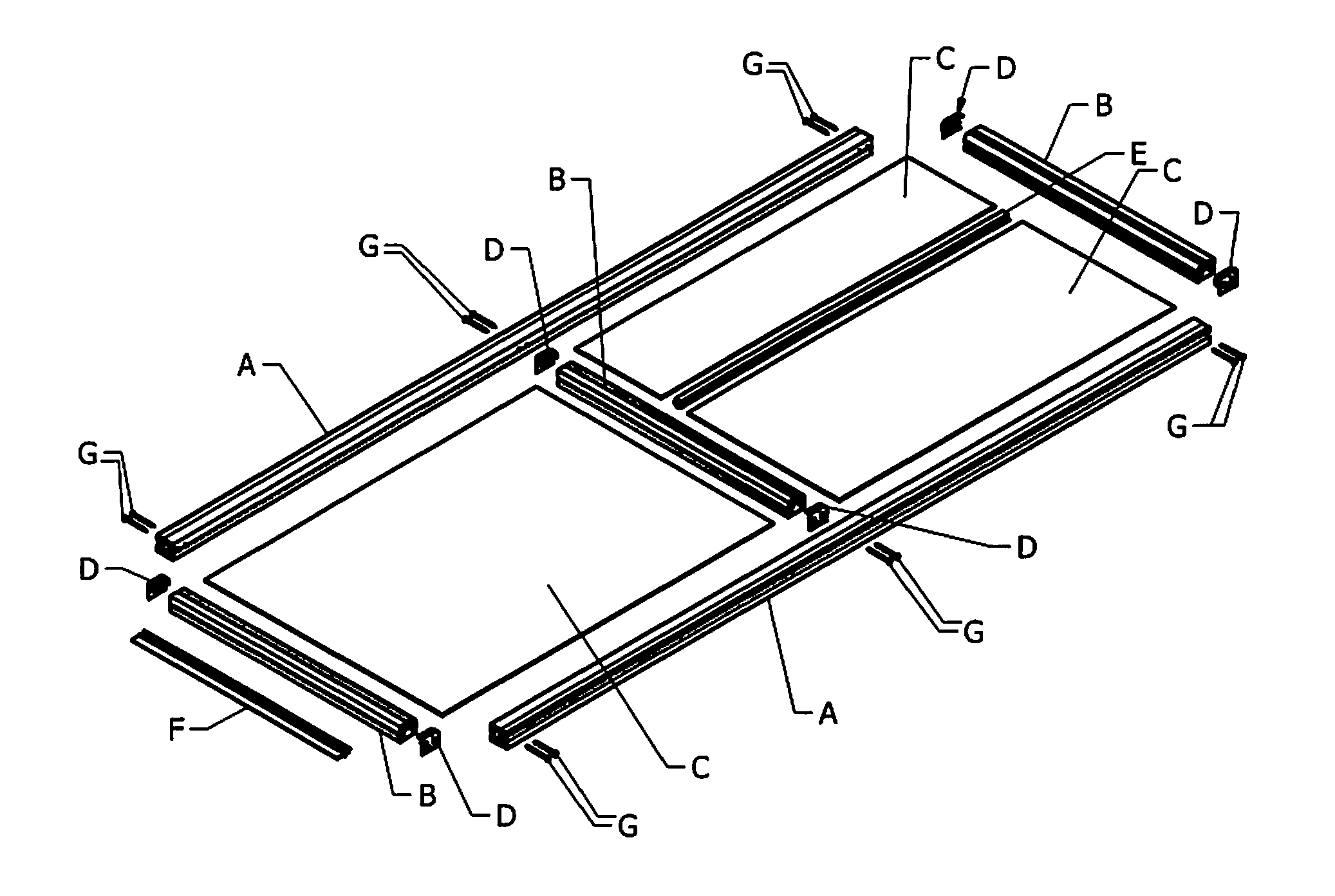
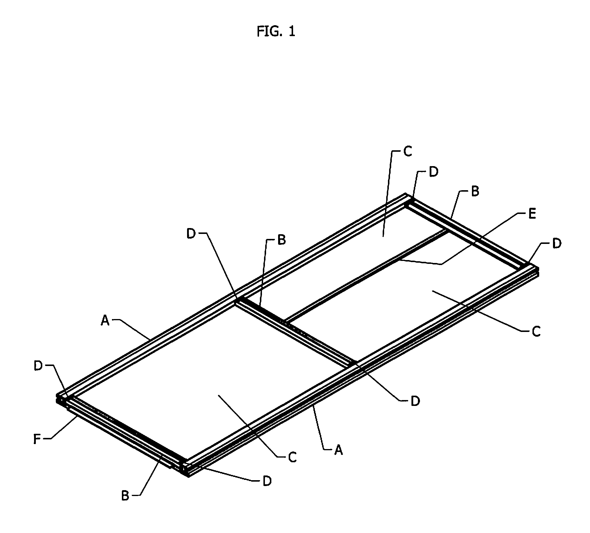
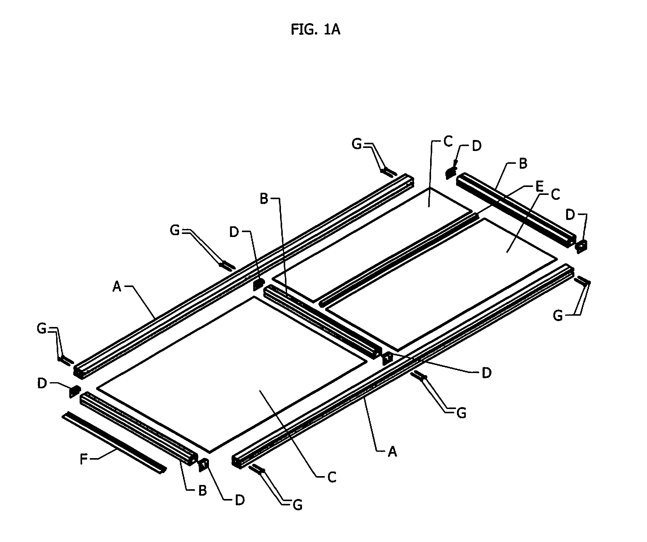
[0052]In the description that follows, it should be understood that when referring to “one partition” can mean either a segment or a plurality of segments formed by the longitudinal profiles (A) and transversal profiles (B) and Panels (C) illustrated in FIGS. 1 and 1A, or the complete set formed by said segments.

[0053]The following describes preferred embodiments of the invention and according to the drawings of FIGS. 1, 1A, 2, 2A, 2B, 2C, 3, 3A, 3B, 3C, 3D, 4, 4A, 5, 6, and 7, with the sole purpose of illustrating it better, but certainly it should be understood that this is not limiting the scope of the same.

[0054]In an especially preferred embodiment, the invention provides a divider, partition, panel or screen comprising a perimetric frame formed by two longitudinal profiles A, FIGS. 1 and 1A, preferably, both hollow as PVC extrudates, fastened with fasteners of the type of screws, rivets, and / or glued or toothed bolts G, FIG. 1A to two transverse profiles B, FIGS. 1 and 1A, als...


PUM

PropertyMeasurementUnit
lengthaaaaaaaaaa
flexibilityaaaaaaaaaa
sizeaaaaaaaaaa

Abstract

A buildable, collapsible and lightweight screen comprising a frame constructed with at least two longitudinal profiles, at least two transverse profiles, hollow extruded profiles and which include at least one inner groove which runs along one side, in a longitudinal direction. Each of said profiles, one or more panels of sheet material are confined within said frame along said inside groove, and connectors that align and fasten the longitudinal and transverse profiles by fasteners, connectors which act as intermediaries to avoid direct contact between these profiles.

Description

FIELD OF INVENTION[0001]The present invention generally relates to structures formed by panels made of rigid or semi-rigid materials associated with frames for the construction of doors, sliding screens, windows, enclosures and the like. More particularly, it relates to novel connectors associated with new profiles whereby screens which are structurally strong, mountable, demountable, lightweight and adjustable by the user are used for the construction of doors, sliding screens, windows, enclosures and other similar structures.BACKGROUND OF THE INVENTION[0002]It is well known that reinforced buildable profiles with different structures made of aluminum and other materials such as window and door profiles were cut square at their ends. They are assembled together by means of screws. They are housed in spaces with previously extruded profiles for the purpose of receiving, wherein the profiles that are assembled orthogonally touch each other. These profiles are frameworks that may also...

Claims


Application Information

Patent Timeline
Patent Type & Authority Applications(United States)
IPC IPC(8): E04C2/38E05D15/06
CPCE05D15/0621E04C2/38E04C2/388
Inventor AGUAYO, JOSE HUMBERTO OROZCO
Owner AGUAYO JOSE HUMBERTO OROZCO
Why Eureka
Try Eureka