
Saw cutting guide

Inactive Publication Date: 2015-02-19
LANE RICHARD P
View PDF47 Cites 11 Cited by
  • Summary
  • Abstract
  • Description
  • Claims
  • Application Information

AI Technical Summary

Benefits of technology

The present invention is a mechanical guide for safely and accurately guiding powered cutting tools along a specific cut line in a workpiece. Unlike previous guides, this invention is portable and can be used with different types of powered cutting tools. The guide has an alignment fence and a sliding guide plate that can be adapted for different powered cutting tools, reducing friction and improving accuracy. The guide can be easily adjusted to different speeds and can include indicia to accurately indicate the cutting tool's position. The technical effects of this invention are improved accuracy, portability, and ease of use with different powered cutting tools.

Problems solved by technology

However, cutting metal beams accurately is typically a slow and time consuming process, especially at a remote worksite.
However, even for highly skilled craftsmen, such cuts must typically be finished with a grinder to remove any burrs resulting during the cutting prior to welding.
Such cutting operations are further complicated by the wide variety of complex cross-sectional shapes that metal building materials commonly possess based upon building requirements.
In contrast, an abrasive saw abrades the metal and creates a great deal of heat in the metal and the cutting blade.
While portable electric metal-cutting circular saws are convenient, because of their light weight, they can also be difficult to use and control.
Their very portability makes it difficult to obtain an accurately positioned, precision straight line crosscut.
However, using highly experienced workers to operate a metal-cutting circular saw adds substantially to construction costs.
Frequently, less experienced workers are used resulting in the need to grind the cut end until suitably straight and flat for welding.
Portable metal-cutting circular saws are also prone to experience a kickback or violent jerking motion if a saw cut is not maintained perfectly aligned.
While utilizing such a metal-cutting chop saw facilitates good quality cross cuts with less experienced labor, there are increased material handling costs.
This not only necessitates additional handling but may idle skilled workers and slow construction while correct replacement materials are obtained.
Moreover, the sheer weight of the metal workpieces further complicates the process, typically making such an operation, particularly in a remote location, impracticable.

Method used


Image

  • Saw cutting guide
  • Saw cutting guide
  • Saw cutting guide

Examples


Embodiment Construction

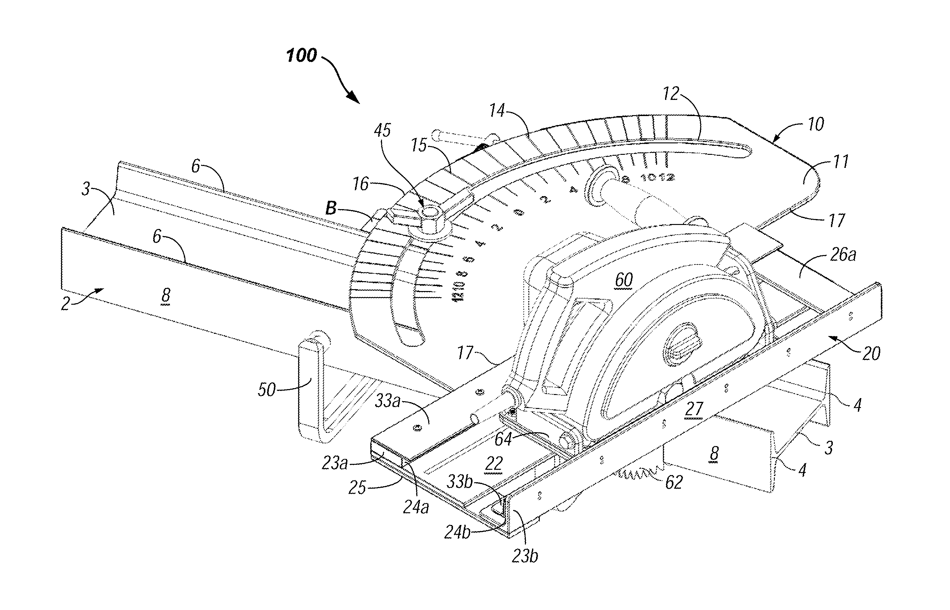
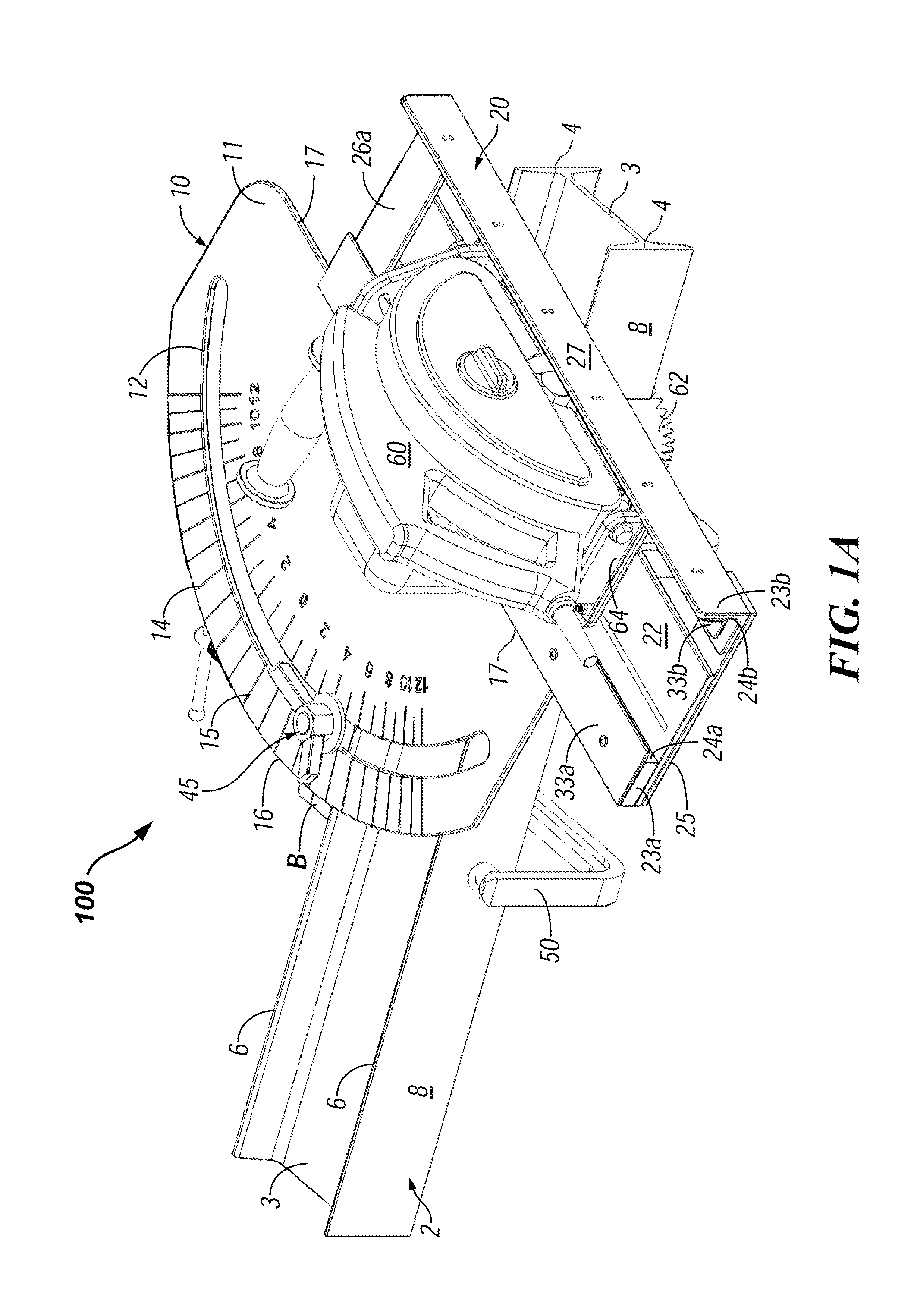
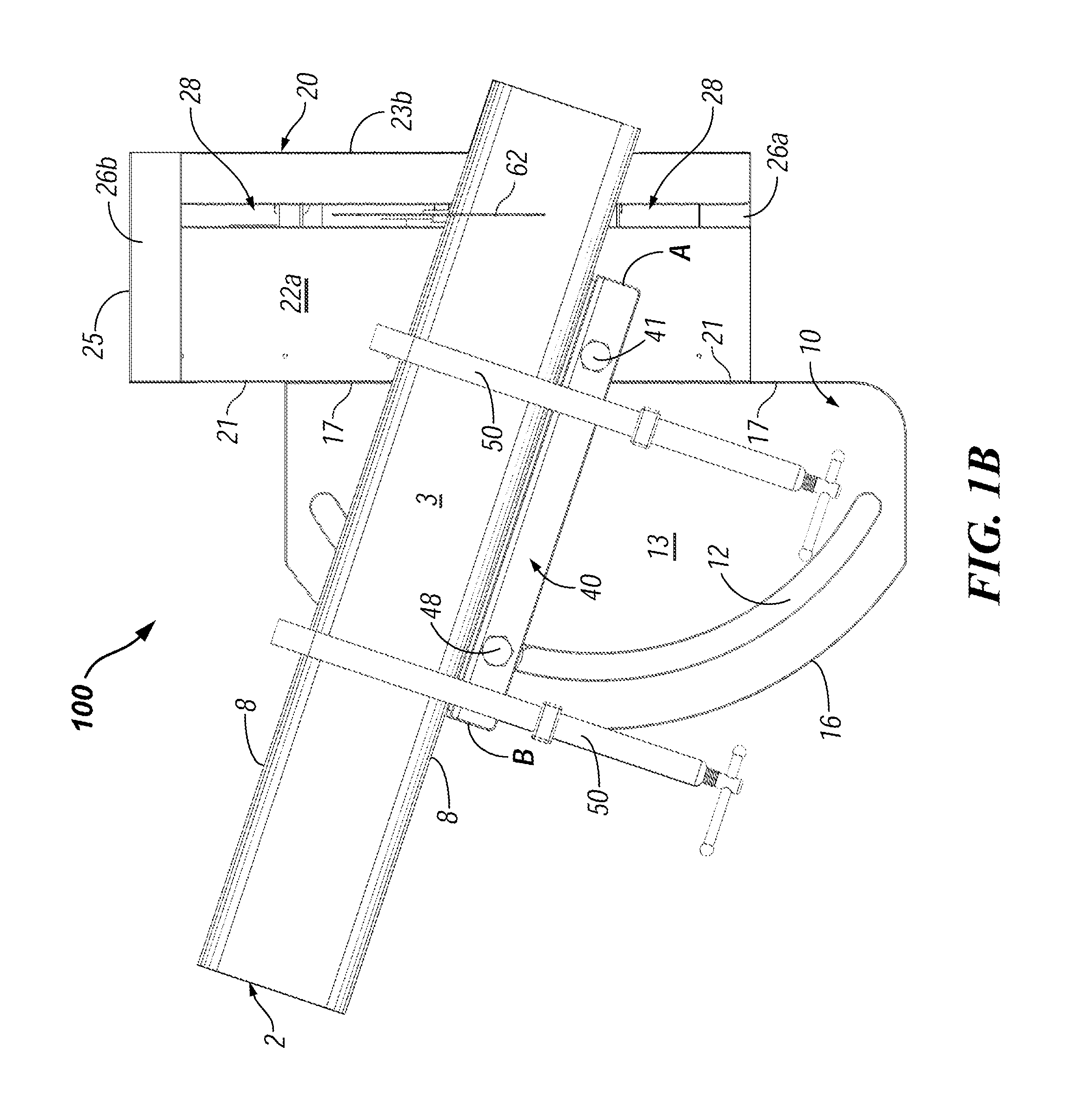
[0028]With reference to the Figures, and in particular FIGS. 1A and 1B, an embodiment of the Saw Cutting Guide device 100 of the present invention is depicted. The device 100 comprises a main base plate 10 having a top side 11 and an underside 13, an adjoining guide track 20 configured on the top side 11 for receiving and guiding a powered hand tool 60 and an alignment fence 40 pivotally mounted to the underside of the device 100 for selectively aligning the work piece in relation to the guide track 20. The device 100 may also include a mechanism for selectively securing or clamping the alignment fence 20 to the main base plate 10. In addition, the device 100 may also include a mechanism for selectively clamping the alignment fence 20 to a workpiece. While a preferred embodiment of the present invention is constructed primarily out of ¼″ metal plate and angle, it is understood that the Saw Cutting Guide of the present invention can be manufactured out of any suitably sturdy and rigi...


PUM

PropertyMeasurementUnit
Angleaaaaaaaaaa
Lengthaaaaaaaaaa

Abstract

The improved saw cutting guide of the present invention overcomes many of the disadvantages of prior art power cutting tools by providing a portable, mechanical guide for safely and accurately guiding a powered cutting tool along a predetermined cut line in the workpiece that is at a desired angular position relative to the cutting blade of the power cutting tool. The saw cutting guide includes a main baseplate having a top side and an under side, and featuring a guide track on the top side, for receiving and guiding a power cutting tool, and a pivotally mounted alignment fence on the underside for selectively aligning the work piece in relation to the guide track. In a preferred embodiment, the power cutting tool comprises an electric circular saw having a metal cutting blade featuring cold saw metal-cutting technology.

Description

BACKGROUND OF THE INVENTION[0001]1. Technical Field of the Invention[0002]This invention generally relates to power tools and, more particularly, to an apparatus and method for guiding a powered hand tool, such as a circular power saw, router, reciprocating sabre saw, or the like, along a predetermined line to be cut in a workpiece. More specifically, the present invention is directed at a portable saw guide that mechanically guides a metal-cutting circular power saw along a predetermined line to be cut in a metal workpiece at a desired angular position relative to the saw blade of the circular power saw.[0003]2. Description of the Related Art[0004]The construction of metal framed buildings often requires cutting mitered cuts in metal building materials. For example, rafter beams need to be cut accurately at a predetermined miter cut or pitch angle prior to being welded to a ridge beam. However, cutting metal beams accurately is typically a slow and time consuming process, especiall...

Claims


Application Information

Patent Timeline
IPC IPC(8): B23D59/00B23D47/02B23D45/00
CPCB23D59/003B23D47/02B23D45/006B27B9/04B23Q9/005Y10T83/849Y10T83/0605Y10T83/8889
Inventor LANE, RICHARD P.
Owner LANE RICHARD P
Learn More