Device and method for harvesting, collecting or capturing and storing ambient energy

a technology of ambient environment and energy storage, applied in the direction of electric variable regulation, process and machine control, instruments, etc., can solve the problems of many major obstacles to capturing rf energy from the ambient environment, complex chips and more power to operate, and battery rfid systems often considered unsuitable for rfid systems

Inactive Publication Date: 2015-02-19
RAFFE TECH
View PDF5 Cites 29 Cited by
  • Summary
  • Abstract
  • Description
  • Claims
  • Application Information

AI Technical Summary

Benefits of technology

[0035]According to another embodiment of the invention, there is provided a device for collecting ambient energy. The device includes at least one ambient energy collecting a

Problems solved by technology

In more recent systems, the chips are more complex and require more power to operate.
As such, batteries are often deemed unsuitable for RFID systems because batteries will frequently become depleted and require charging before using.
However, there are many major obstacles for capturing RF energy from the ambient environment.
There are several drawbacks with this standard concept design in the prior art, which may be linked to the transmitter network and the receiver network.
For example, it

Method used


Image

  • Device and method for harvesting, collecting or capturing and storing ambient energy
  • Device and method for harvesting, collecting or capturing and storing ambient energy
  • Device and method for harvesting, collecting or capturing and storing ambient energy

Examples


Embodiment Construction

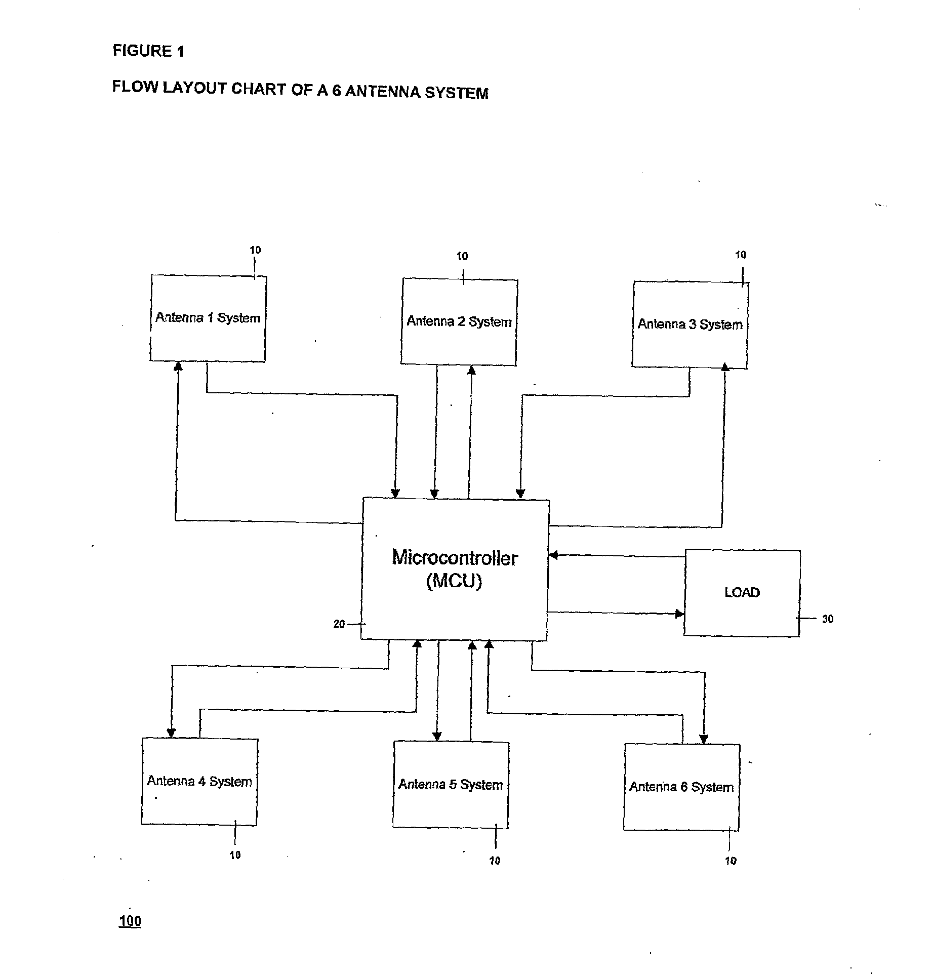
[0058]Referring now in more detail to the drawings, in which like numerals refer to like parts throughout the several views, FIG. 1 is a flow chart of a six antenna system of the ambient energy collector device 100 of the present invention. The ambient energy collector device 100 preferably includes a plurality of antenna systems 10 and a master controller unit 20. The master controller unit 20 may be connected to each antenna system 10 and to a load 30. In a preferred embodiment, the device may include six antenna systems 10. The antenna system 10 is also referred to as an Ambient RF Energy Power Cell.

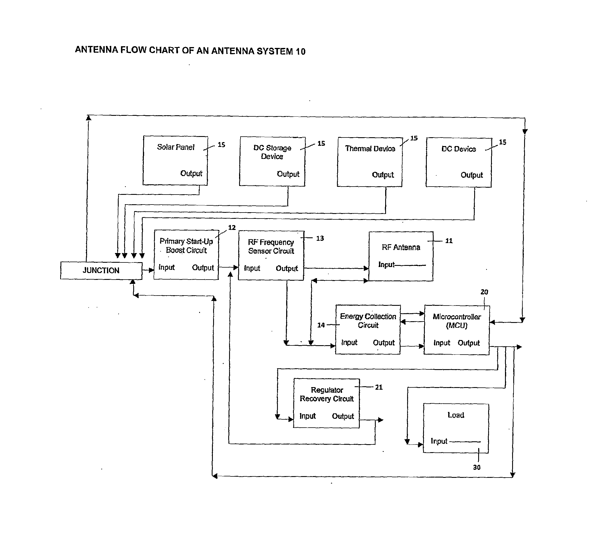
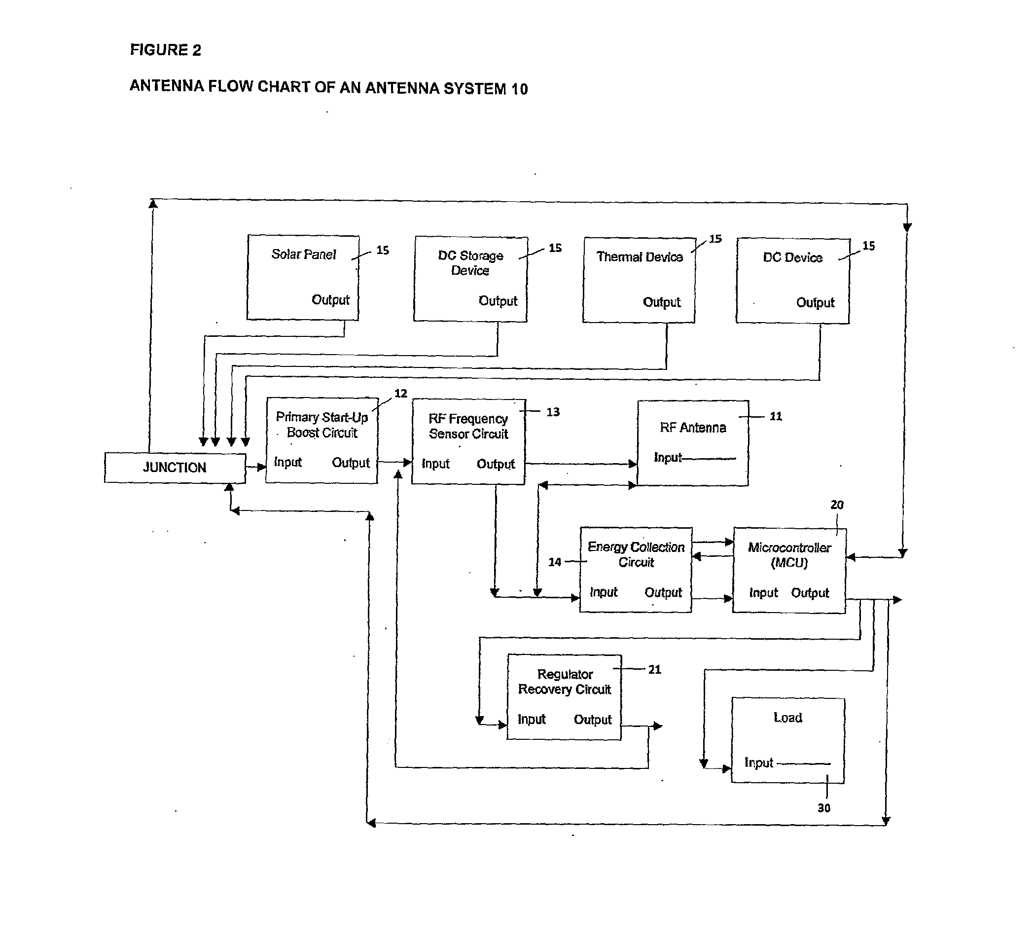
[0059]FIG. 2 shows a preferred embodiment of a flow chart of an antenna system an architectural arrangement of the circuitry that pertains to one of the layers of the antenna system 10. In the figures embodied herein, each block pertains to a circuit and the blocks are connected by arrows to show the input and output of each block.

[0060]The invention is preferably implemented as a mul...


PUM


Abstract

An ambient energy collector for use in AC/DC applications is described. The ambient energy collector has at least one ambient energy collecting antenna system and a master control unit for operational control of the at least one ambient energy collecting antenna system. The ambient energy collector has a DC voltage boosting circuit for increasing an input voltage, a DC primer power source for powering up the voltage boosting circuit via the input voltage, at least one antenna system for collecting ambient energy, an energy collection circuit for converting and amplifying an AC voltage collected by the antenna of the at least one antenna system into a DC voltage, and an output circuit for providing a load with the DC voltage.

Description

TECHNICAL FIELD OF THE INVENTION[0001]The present invention relates generally to the harvesting, collecting or capturing of ambient energy and storing the energy for use in AC / DC applications. More particularly, the present invention relates to a multi-layer energy collection system and method for powering and / or charging electronic devices.BACKGROUND OF THE INVENTION[0002]Energy harvesting devices have been known and used to capture and store energy in the form of electrical power for small autonomous devices such as, for example, wireless sensor devices and radio frequency identification (RFID) tags.[0003]For example, it is known to use an antenna for radio frequency capture. The conventional devices use the antenna as input into a charge-pump circuit and then use the captured energy for powering other electronic circuits. Such a conventional device has been used in Radio Frequency Identification (RFID) applications. With an RFID system, a chip is inserted inside an RFID tag. When...

Claims


Application Information

Patent Timeline
IPC IPC(8): H02J5/00H02M7/10H02J7/02G05F1/62H02J17/00H02J7/00H02J50/20
CPCH02J5/005H02J17/00H02M7/10H02J7/025G05F1/62H02J7/0055H02M1/36H02M7/103H01Q1/248H01Q21/00H01Q1/36H01Q7/005H02J50/20H02J7/00712H02J50/402H02J50/001H02J50/27H02J2207/40
Inventor MURLEY, ALAN JOSEPH
Owner RAFFE TECH
Why Eureka
Try Eureka