Lamp unit power supply system

a technology for power supply systems and led lamps, applied in emergency power supply arrangements, electric vehicles, electrical appliances, etc., can solve the problems of disadvantageous provisioning of two drivers and difficulty in adding emergency mode functionality to existing lighting systems, and achieve the effect of fast time to market and flexibility

Inactive Publication Date: 2015-02-19
TRIDONIC UK
View PDF4 Cites 29 Cited by
  • Summary
  • Abstract
  • Description
  • Claims
  • Application Information

AI Technical Summary

Benefits of technology

[0009]The system may include controllable switch means operable to selectively provide mains power to the mains input of the driver in the normal mode and power from the charge storage device to the mains input of the driver in the emergency mode. In this way, the driver and the lamp unit may be powered in both the normal mode and the emergency mode. The emergency mode converter may be controlled in a way that

Problems solved by technology

Providing two drivers is disadvantageous for cost and space reasons.
Also, the requirement for a separate driver to drive the LED lam

Method used


Image

  • Lamp unit power supply system
  • Lamp unit power supply system

Examples


Embodiment Construction

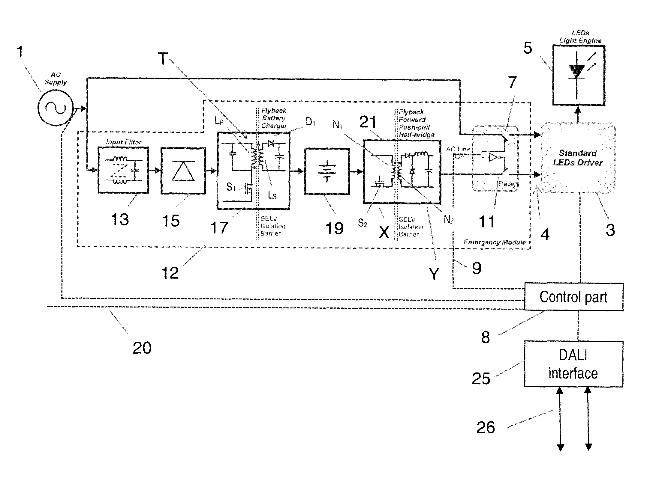
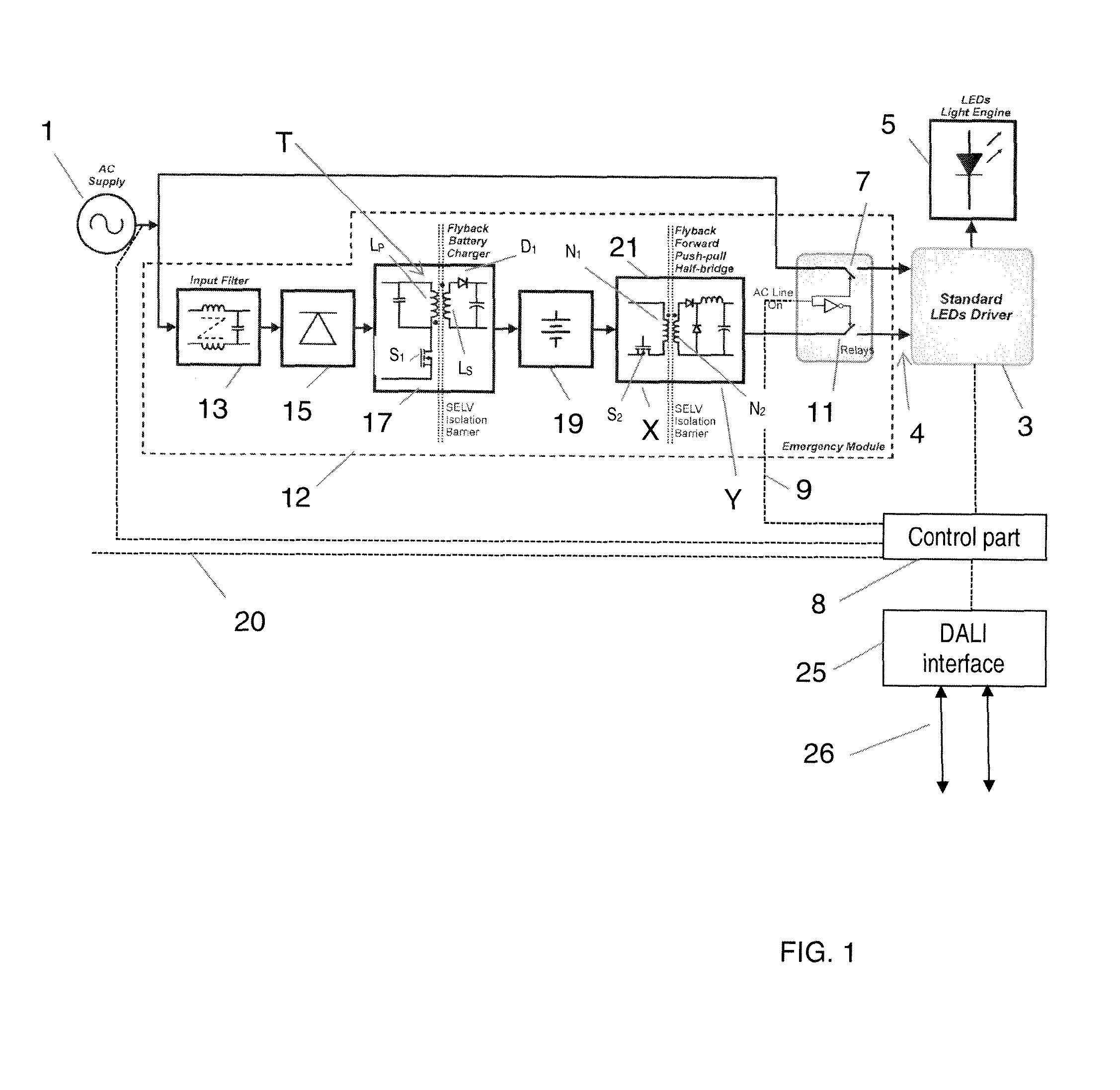
[0013]FIG. 1 shows schematically the elements of a lighting arrangement that provides both a normal mode and an emergency lighting mode. A direct mains AC supply 1 provides power in the normal mode to a driver 3 optimised for use with the mains supply 1 (e.g. 230 volts, 50 Hz in the EU).

[0014]The driver 3 is supplied with power at a mains input 4 when a mains relay 7 is closed. A control part 8 monitors the mains AC supply 1. If the control part 8 detects that the mains AC supply 1 is interrupted, or if it is determined to be malfunctioning (operating outside an acceptable range of values), the control part 8 may provide an appropriate signal to relay control line 9 to open the mains relay 7 and to close an emergency relay 11. The emergency relay 11 allows the lamp 5 to be driven in an emergency mode. The driver 3 is preferably an independent driver which is only connected to the mains AC supply through the mains relay 7 which is closed when mains AC supply is available. In a prefer...


PUM


Abstract

A power supply system for illuminating an LED lamp unit 5, having a normal mode of operation in which a mains input 4 of a driver 3 of the LED lamp unit is supplied by mains power 1, and an emergency mode of operation, in which the LED lamp unit is supplied by a charge storage device 19, is disclosed. The system includes an emergency mode converter 21 operable to step-up the voltage from the charge storage device and to supply the mains driver input for illuminating the LED lamp unit.

Description

TECHNICAL FIELD[0001]The present invention relates to power supply system and method for illuminating an LED lamp unit, having a normal mode of operation in which a mains input of a driver of the LED lamp unit is supplied by mains power, and an emergency mode of operation, in which the LED lamp unit is supplied by a charge storage device.BACKGROUND TO THE INVENTION[0002]Various arrangements for lighting systems are known which provide both conventional and emergency lighting. Such emergency lighting is intended to be activated when the conventional lighting is no longer operative because the direct mains supply to the conventional lighting is no longer available or malfunctions. Emergency lighting is typically powered by a battery or other energy storage device. Conventional lighting is controlled by an on / off switch by means of which a user (or control system) can control whether the lighting is illuminated or not. Generally, emergency lighting is intended to be automatically illum...

Claims


Application Information

Patent Timeline
IPC IPC(8): H05B33/08H02J7/02H02J9/06H05B44/00
CPCH05B33/0809H02J7/02H02J9/061H02J9/062H05B45/385H05B45/38H05B45/39
Inventor WILSON, IAN
Owner TRIDONIC UK
Why Eureka
Try Eureka