Stream data processor

a data processor and data technology, applied in the field of data processors in computing systems, can solve the problems of inefficient implementation of data parallelism from instruction code, inability to adapt to the product requirements, and inability to implement software tools that map high level c code to the platform in an efficient way, so as to achieve the best die size and power efficiency, the effect of fast time to mark

Active Publication Date: 2014-05-01
MEDIATEK INC
View PDF10 Cites 2 Cited by
  • Summary
  • Abstract
  • Description
  • Claims
  • Application Information

AI Technical Summary

Benefits of technology

[0024]To combine the advantages of dedicated hardware with the advantages of conventional SDR solutions, each of a plurality of SDPs is partitioned into one or more Stream Processor Units (SPU) and a Stream Control Unit (SCU). The SPU implements processing functions in dedicated hardware and is hence die size and power efficient. The bit width of the operands can be optimised for the specific application being targeted. The size of the data memory associated with the SPU is comparable to that used if the complete baseband was implemented using dedicated hardware. This makes the SDP solution much more die size efficient than a conventional SDR solution.
[0025]The SCU performs the sequencing of the processing functions. There are different implementation options for the SCU which range from the flexibility of a conventional SDR solution to the die size efficiency of a dedicated hardware solution. A flexible software defined SCU can be chosen to minimise the time to market of the product. An SCU based on dedicated hardware can be used for later versions of the product, to minimise die size.
[0030]The SCU provides the configuration data for the SPU. One SCU solution is to use a dedicated microprocessor to configure one or more SPUs. A configuration register block implements a double buffer enabling the SPU to operate using one configuration whilst the next is prepared, thus minimising SPU idle time. One advantage of using a microprocessor as the configuration controller is that the SPU and the microprocessor can share the data memory reducing data transfer overhead.
[0033]SDR based implementations offer a fast time to market. Dedicated hardware designs usually lead to the best die size and power efficiency. There is however no straight forward migration path between these two methodologies. A computing system based on a plurality of SDPs solves this problem. Each SDP is separated into an SPU implemented in dedicated hardware for data processing and an SCU for configuration. The SPU is die size and power efficient. Different implementation options for the SCU offer a trade-off between flexibility and die size and power efficiency.

Problems solved by technology

Product requirements do however tend to change over time.
The problem with CGRA is that it is very difficult to, e.g., implement software tools that map high level C code onto the platform in an efficient way.
One issue with VLIW architectures is that they are quite inefficient at implementing data parallelism from an instruction code size point of view.
Almdahl's law states that there is an upper limit to the effectiveness of the speeding up of subtasks.
This is not very helpful in the embedded context, because time-sharing increases overhead.
For an SDR solution, there are typically hard time limits by which a certain number of tasks must have completed.
This is however quite expensive.
The maximal speedup achievable in practice is limited by the interdependencies within the sub-tasks.
The cost for the extra hardware is limited due to the reuse.
Almdahl's law does however put an upper limit on the achievable overall speed increase.
SDR solutions are commonly limited to using 8, 16, 32 and 64 bit operands.
SDR solutions hence use larger than necessary operands and are hence less die size and memory area efficient than dedicated hardware.
The digital baseband has to perform de-interleaving operations, but this is difficult to implement efficiently on a processor that operates on short vectors, as multiple iterations of shuffle operations are required to process large data packets.

Method used


Image

  • Stream data processor
  • Stream data processor
  • Stream data processor

Examples


Embodiment Construction

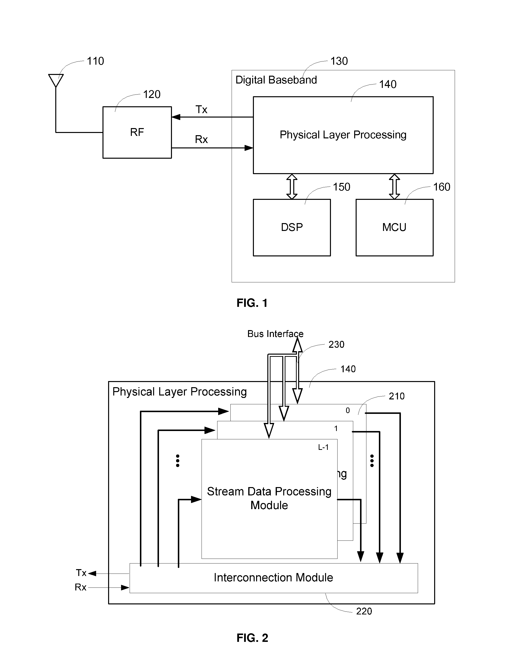
[0046]The digital baseband (DBB) part of a User Equipment (UE) handles the digital signal processing required in the physical layer (PHY) of the UE's radio system. FIG. 1 shows a simplified block diagram of a digital baseband solution that may be configured in accordance with embodiments described herein. The antenna 110 and RF module 120 of the UE handle the radio frequency data transmission and reception including up-converting the baseband signal for transmission and down-converting the received signals into a baseband signal. The digital data processing is handled by the digital baseband module 130, which typically comprises a physical layer processing unit 140, a DSP 150, and a microcontroller unit (MCU) 160. The MCU is used to control the functions of the DBB while the DSP is used for further signal processing not handled by the PHY layer.

[0047]In order to achieve the low cost and power consumption required, the digital baseband processing must be optimized for the types of op...


PUM


Abstract

Techniques are provided aimed at improving the flexibility and reducing the area and power consumption of digital baseband integrated circuits by using stream data processor based modem architecture. Semiconductor companies offering baseband ICs for handsets, face the challenges of improving die size efficiency, power efficiency, performance, time to market, and coping with evolving standards. Software defined radio based implementations offer a fast time to market. Dedicated hardware designs give the best die size and power efficiency. To combine the advantages of dedicated hardware with the advantages of conventional software defined radio solutions the stream data processor is partitioned into a stream processor unit, which implements processing functions in dedicated hardware and is hence die size and power efficient, and a flexible stream control unit which may be software defined to minimise the time to market of the product.

Description

FIELD OF THE INVENTION[0001]The present disclosure relates to data processors in computing systems and more particularly to techniques aimed at improving the flexibility and reducing the area and power consumption of digital baseband integrated circuits in wireless communications systems by using a stream data processor based modem architecture.BACKGROUND OF THE INVENTION[0002]Semiconductor companies offering baseband ICs for handsets, face the following challenges: die size, power efficiency, performance, time to market, inter- / intra-RAT (Radio Access Technology) multimode support and evolving standards. Dedicated hardware designs have been used in the past, because they give the best die size and power efficiency. A recent trend is to employ software-defined radio (SDR) based implementations, because they offer a fast time to market. Which methodology is the most advantageous depends on the product requirements. Product requirements do however tend to change over time. Flexibility...

Claims


Application Information

Patent Timeline
Patent Type & Authority Applications(United States)
IPC IPC(8): G06F9/46
CPCG06F9/46G06F15/8015
Inventor KUECHLER, WOLFGANG
Owner MEDIATEK INC
Why Eureka
Try Eureka