Stator and rotor for an electric machine

a technology of electric machines and stators, applied in the field of electric machines, can solve the problems of low speed, low manufacturing cost, and limited size of claw pole machines, and achieve the effect of efficient and robust assembly

Inactive Publication Date: 2015-02-19
HOGANAS AB
View PDF5 Cites 22 Cited by
  • Summary
  • Abstract
  • Description
  • Claims
  • Application Information

AI Technical Summary

Benefits of technology

[0012]Embodiments of the stator disclosed herein allow for a robust construction of an electric machine such as a Claw Pole type machine.
[0039]In some embodiments the permanent magnets may be magnetised in radial direction. For example, embodiments of the rotor may comprise a plurality of surface mounted permanent magnets. The rotor may comprise a core back, e.g. made of mild steel, thus resulting in a simple construction that allows easy assembly. The rotor may be further simplified by using a Hallbach magnetisation arrangement of the permanent magnets, thus allowing the rotor core back to be omitted.

Problems solved by technology

However, one of the drawbacks of the design is that they are often relatively expensive to manufacture.
Currently claw pole machines are restricted to a small size and / or low speed if the stator is constructed completely from steel as typical machines used as car alternators are.
Cogging torque refers to the undesirable torque due to the interaction between permanent magnets of the rotor and the stator.

Method used


Image

  • Stator and rotor for an electric machine
  • Stator and rotor for an electric machine
  • Stator and rotor for an electric machine

Examples


Embodiment Construction

[0069]In the following description, reference is made to the accompanying figures, which show by way of illustration how the invention may be practiced. Throughout the drawings, like reference numerals refer to like or corresponding components, elements, and features.

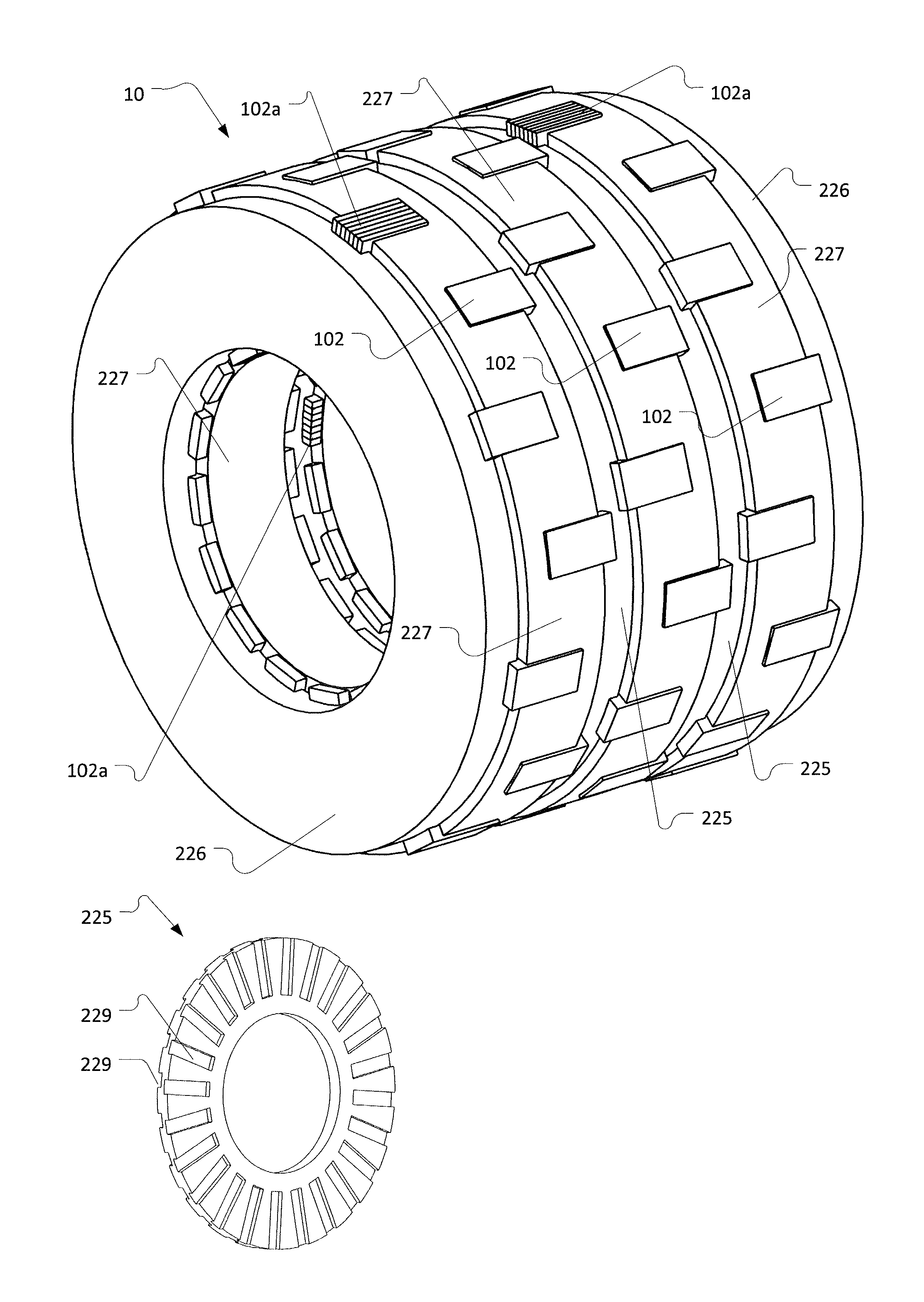
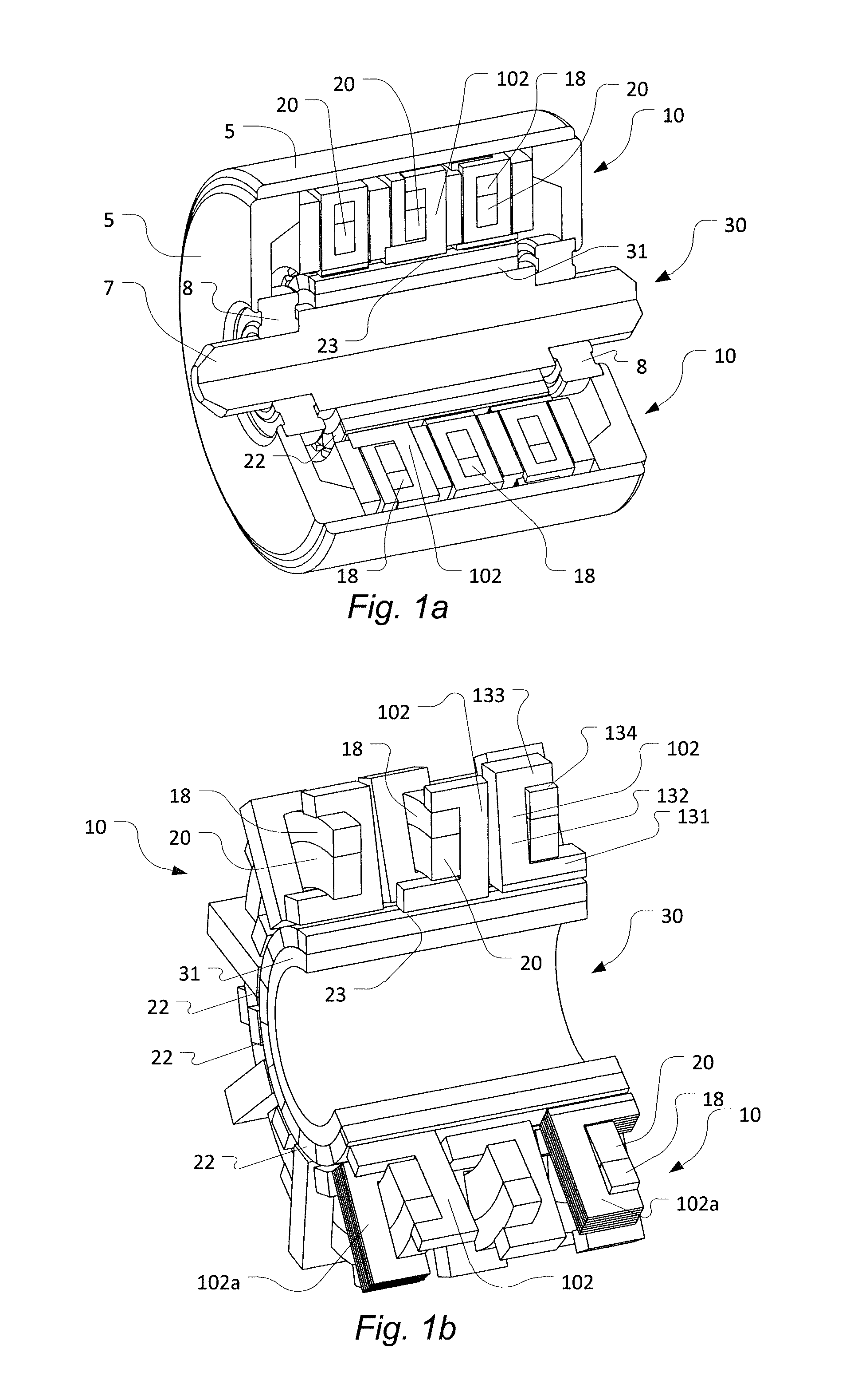
[0070]FIGS. 1a and b illustrate an example of a 3-phase inner-rotor modulated pole machine. In particular, FIG. 1a shows a perspective view of an electric machine with a portion of the machine cut away, while FIG. 1b shows a corresponding view of the magnetically active parts of the machine.

[0071]The machine comprises a housing 5, a stator 10 and a rotor 30 arranged inside the housing such that a rotor shaft 7 axially protrudes out of the housing 5, supported by bearings 8 so as to allow the rotor to rotate relative to the housing. The stator 10 and the rotor 30 are encircling a common geometric axis, defined by the rotor shaft 7. The rotor and the stator define an active air gap 23 between them so as to allow the commu...


PUM

PropertyMeasurementUnit
coercivityaaaaaaaaaa
particle sizesaaaaaaaaaa

Abstract

A stator for an electric machine, the stator including a stator core and a winding. The stator core including an annular stator core back component providing a magnetic flux path in a circumferential direction and in an axial direction of the annular stator core back component; and a plurality of stator pole components each including a mounting part mounted to the stator core back component, an interface part defining an interface surface facing an active air gap between the stator and a rotor of the electrical machine; and a radially oriented tooth part extending radially from the annular stator core component and connecting the interface part with the mounting part.

Description

FIELD OF THE INVENTION[0001]This invention generally relates to electric machines and, in particular, to modulated pole machines. More particularly, the invention relates to a stator and to a rotor for such an electric machine.BACKGROUND OF THE INVENTION[0002]Over the years, electric machine designs such as modulated pole machines, e.g. claw pole machines, Lundell machines and transverse flux machines (TFM) have attracted increased interest. Electric machines using the principles of these machines were disclosed as early as 1890 in U.S. Pat. No. 437,501 and about 1910 by Alexandersson and Fessenden. One of the reasons for the increasing interest is that the design enables a very high torque output in relation to, for instance, induction machines, switched reluctance machines and even permanent magnet brushless machines. Further, such machines are advantageous in that the coil is often easy to manufacture. However, one of the drawbacks of the design is that they are often relatively ...

Claims


Application Information

Patent Timeline
Patent Type & Authority Applications(United States)
IPC IPC(8): H02K1/14H02K15/02H02K1/27
CPCH02K1/145H02K15/022H02K1/27H02K1/141H02K21/145Y10T29/49009
Inventor NORD, GORANWASHINGTON, JAMIE
Owner HOGANAS AB
Why Eureka
Try Eureka