
Power converter with a multi-level bridge topology and control method

Active Publication Date: 2015-02-19
GENERAL ELECTRIC CO
View PDF8 Cites 11 Cited by
  • Summary
  • Abstract
  • Description
  • Claims
  • Application Information

AI Technical Summary

Benefits of technology

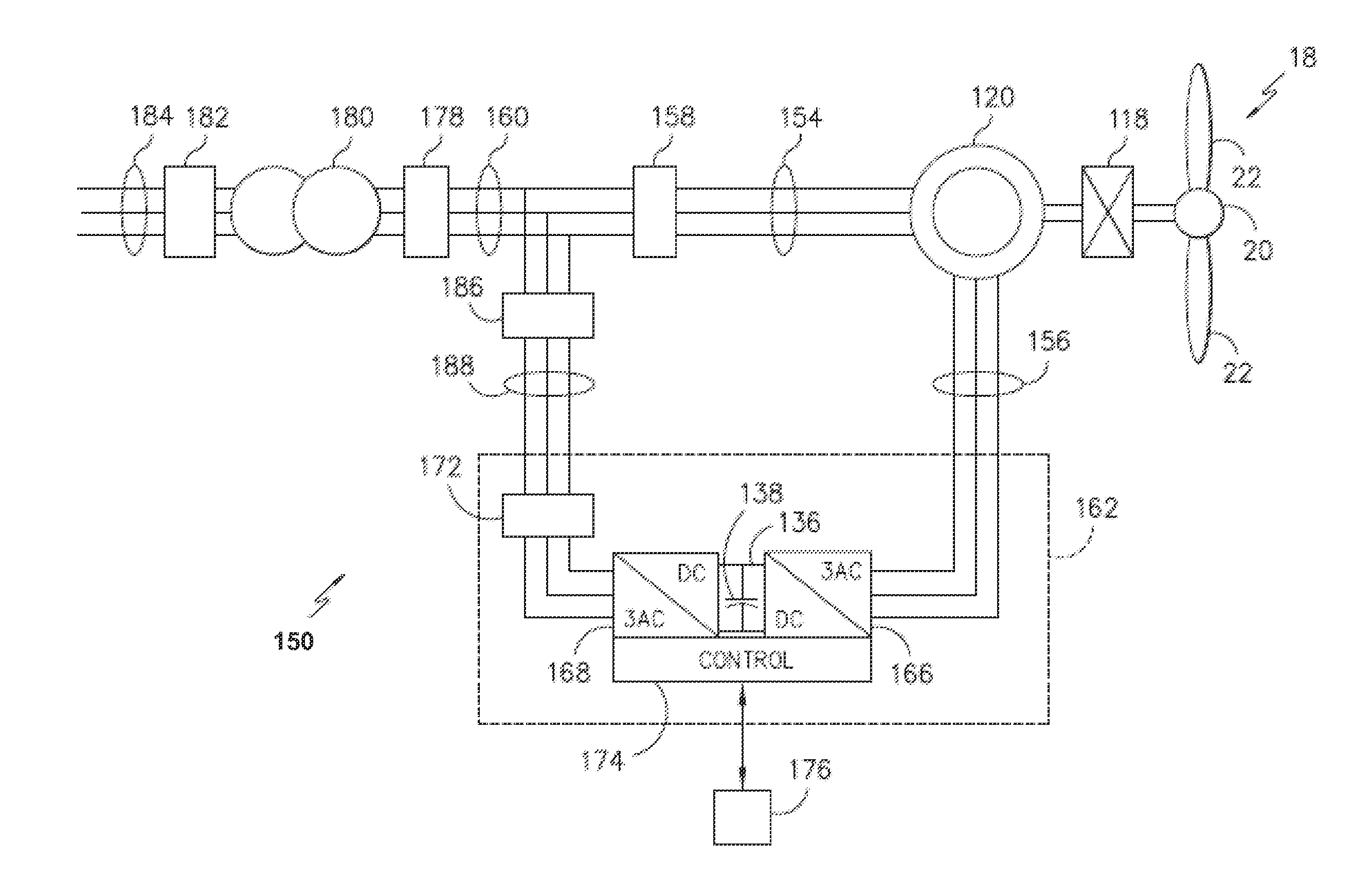
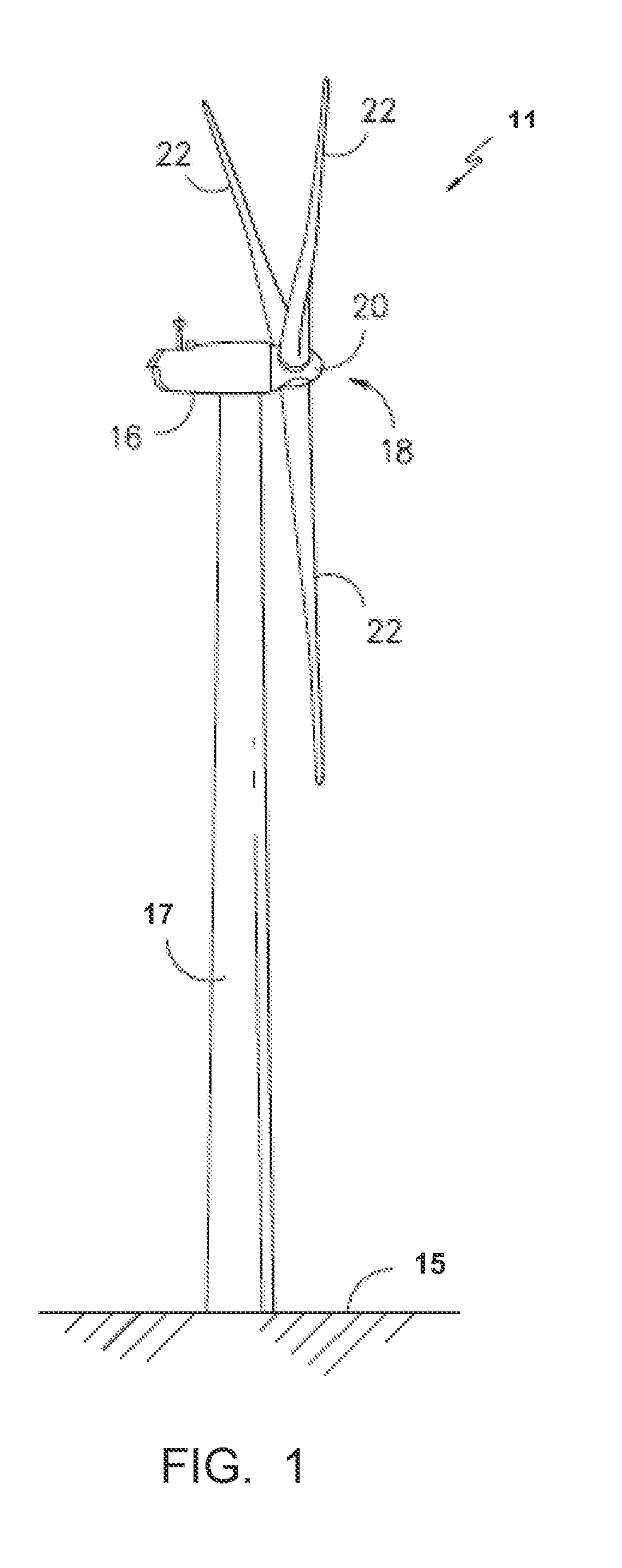
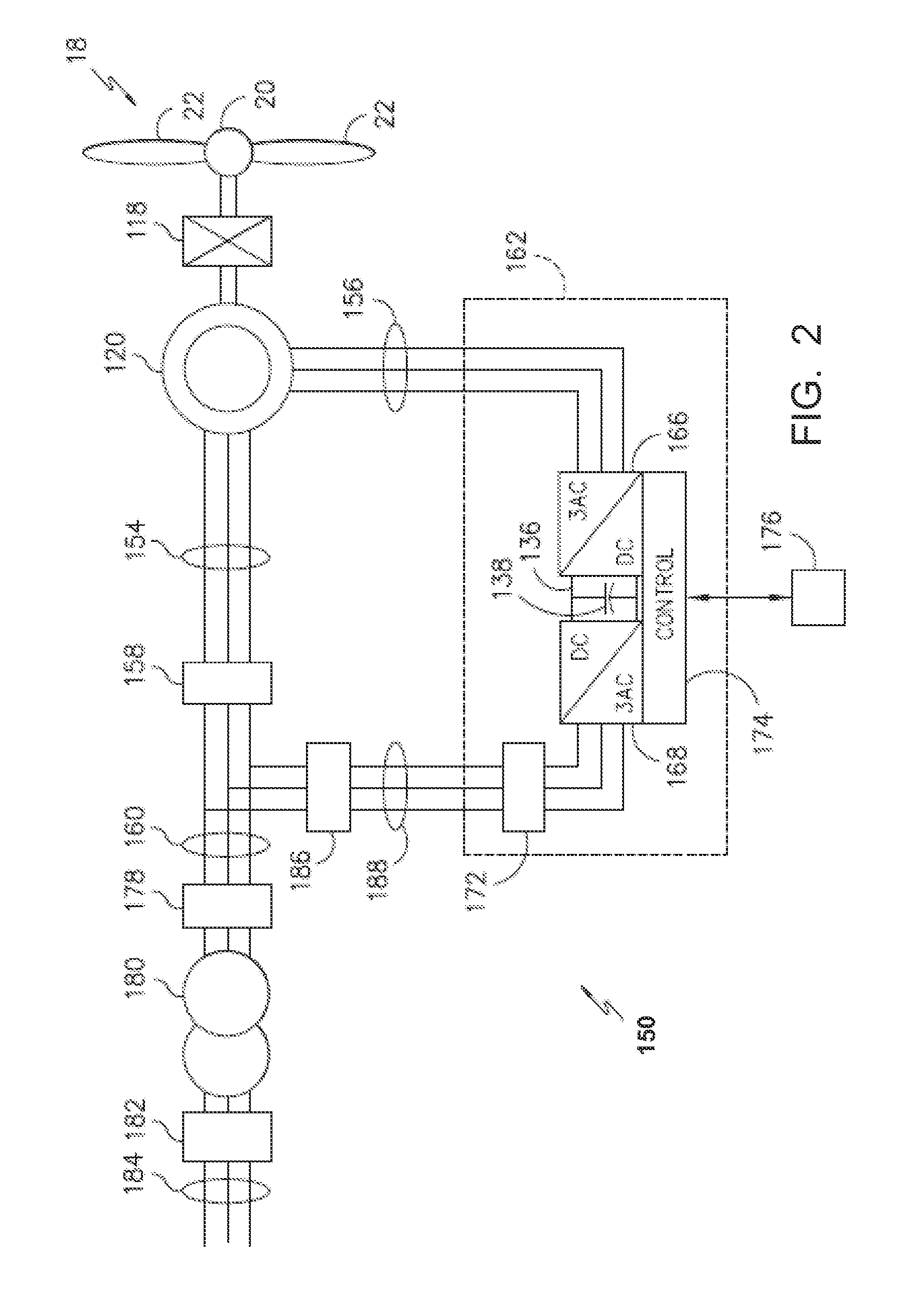
The present invention is related to a power converter that is used in a wind turbine power generation system. The power converter has multiple voltage levels points and a multi-level bridge circuit that connects these points using pairs of switches. The switches are controlled to produce a variable frequency waveform. The technical effect of this invention is to improve the performance and efficiency of wind turbine generators.

Problems solved by technology

Power converters that use switch mode, voltage sourced, Pules Width Modulation (PWM) methods to replace fixed speed mechanically throttled processes have been restricted to a severe tradeoff between operability and efficiency.
Large and costly, as well as wasteful, passive filters have been a part of the limits.

Method used


Image

  • Power converter with a multi-level bridge topology and control method
  • Power converter with a multi-level bridge topology and control method
  • Power converter with a multi-level bridge topology and control method

Examples


Embodiment Construction

[0022]As discussed in the Summary of the Subject Matter section, the present subject matter is particularly concerned with providing frequency adjustable output waveforms for power converters.

[0023]Reference now will be made in detail to embodiments of the invention, one or more examples of which are illustrated in the drawings. Each example is provided by way of explanation of the invention, not limitation of the invention. In fact, it will be apparent to those skilled in the art that various modifications and variations can be made in the present invention without departing from the scope or spirit of the invention. For instance, features illustrated or described as part of one embodiment can be used with another embodiment to yield a still further embodiment. Thus, it is intended that the present invention covers such modifications and variations as come within the scope of the appended claims and their equivalents.

[0024]In accordance with the present subject matter, it has been ...


PUM


Abstract

The present subject matter is directed to apparatus and methods for producing a variable frequency output waveform from a power converter for use in a power generation system, such as a wind turbine power generation system. A voltage divider is employed to provide plural voltage levels to which a multi-level bridge circuit employing selectively activated switches in pairs of switches is coupled. The switches are operated in such a fashion as to produce a generally sinusoidal waveform that may be easily filtered by low cost filters due to the plural voltage levels to produce a generally smooth sine wave from the converter. Such converters may be used in various environments including in pairs in multi-phase power converters.

Description

FIELD OF THE SUBJECT MATTER[0001]The present subject matter relates generally to the field of power converters in power generation systems, and, more particularly, to systems and methods for providing frequency adjustable output waveforms from such power converters.BACKGROUND OF THE SUBJECT MATTER[0002]Power generation systems often include a power converter that is configured to convert an input power into a suitable power for application to a load, such as a generator, motor, electrical grid, or other suitable load. For instance, a power generation system, such as a wind turbine system, may include a power converter for converting variable frequency alternating current power generated at the generator into alternating current power at a grid frequency (e.g. 50 Hz or 60 Hz) for application to a utility grid.[0003]Power converters that use switch mode, voltage sourced, Pules Width Modulation (PWM) methods to replace fixed speed mechanically throttled processes have been restricted t...

Claims


Application Information

Patent Timeline
IPC IPC(8): H02M5/458
CPCH02M5/458H02M7/483H02M7/487Y02E10/76H02M1/088H02M1/007
Inventor WAGONER, ROBERT GREGORYRITTER, ALLEN MICHAEL
Owner GENERAL ELECTRIC CO
Features
  • Generate Ideas
  • Intellectual Property
  • Life Sciences
  • Materials
  • Tech Scout
  • Unparalleled Data Quality
  • Higher Quality Content
  • 60% Fewer Hallucinations
Learn More