Method and apparatus for filter bank multi-carrier signal transmission and channel estimation

a multi-carrier, signal transmission technology, applied in multi-frequency code systems, transmission path sub-channel allocation, baseband system details, etc., can solve the problems of partially counteracting the benefit of the fbmc system and reducing so as to improve the channel estimation performance, reduce the efficiency of pilot overhead, and improve the spectral efficiency of the system

Inactive Publication Date: 2015-02-19
ALCATEL LUCENT SAS
View PDF6 Cites 31 Cited by
  • Summary
  • Abstract
  • Description
  • Claims
  • Application Information

AI Technical Summary

Benefits of technology

[0024]In the present invention, by using the pilot preamble symbol that only occupies one FBMC modulation symbol for each transmit antenna, and using a corresponding channel estimation method at the receiving side, the pilot overhead is reduced efficiently and the spectral efficiency of the system is improved; meanwhile, it is indicated via the computer simulation that the present invention can achieve a better channel estimation performance than the existing IAM method. In other words, the present invention achieves both the beneficial effects of reducing overhead and improving performance simultaneously.

Problems solved by technology

The main problem of the IAM method is that as shown in FIG. 1, the pilot preamble symbol used by IAM needs to occupy at least 3 FBMC modulation symbols (two FBMC modulation symbols are equivalent to one OFDM modulation symbol), and this pilot overhead greatly reduces the spectral efficiency of the system, and to some extent even partially counteracts the benefit of the FBMC system over the existing OFDM system.

Method used


Image

  • Method and apparatus for filter bank multi-carrier signal transmission and channel estimation
  • Method and apparatus for filter bank multi-carrier signal transmission and channel estimation
  • Method and apparatus for filter bank multi-carrier signal transmission and channel estimation

Examples


first embodiment

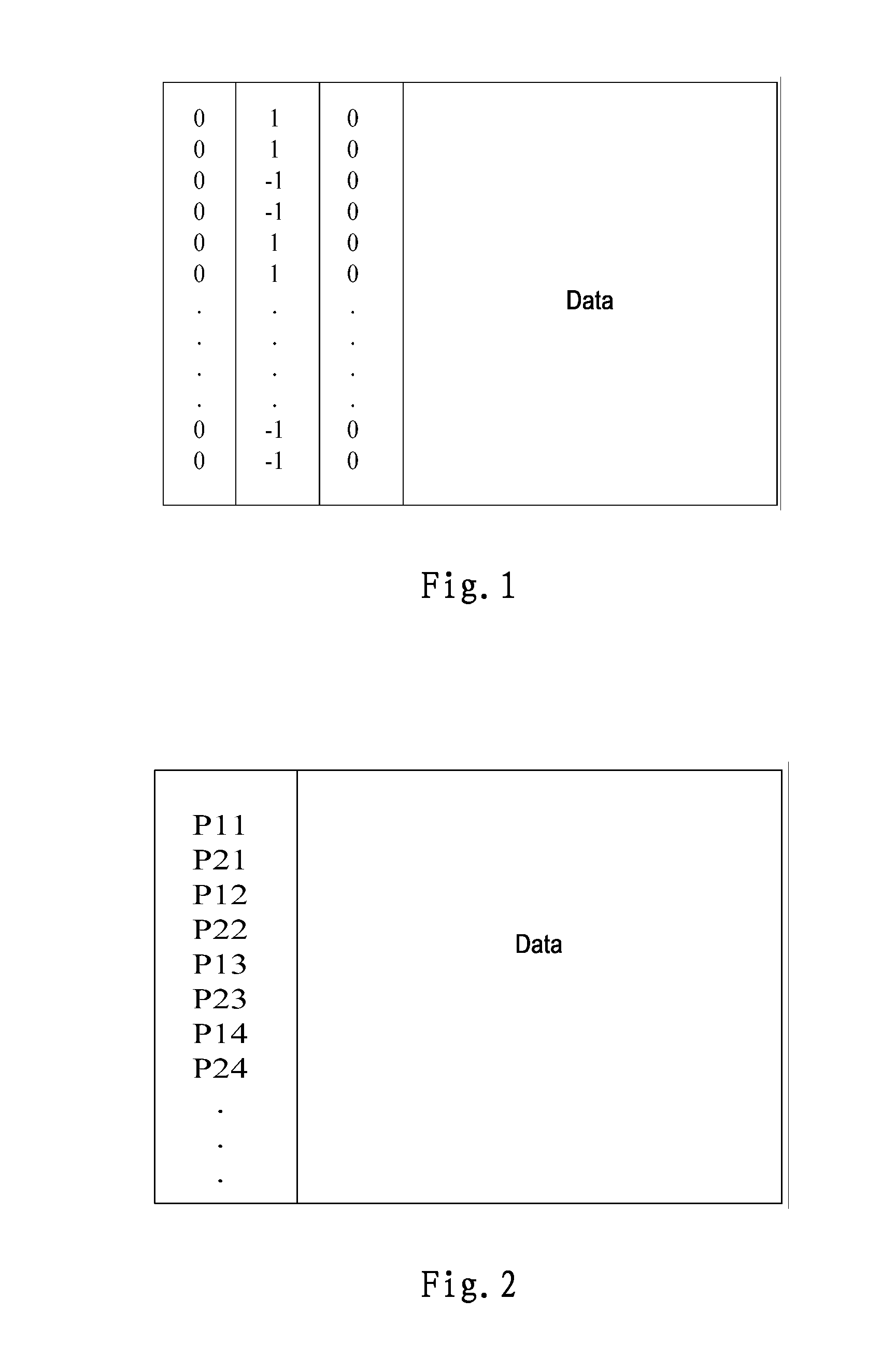
[0041]In the following embodiment, it is discussed that the preamble elements are mapped to the subcarriers equally spaced.

[0042]Design of Pilot Preamble Symbols:

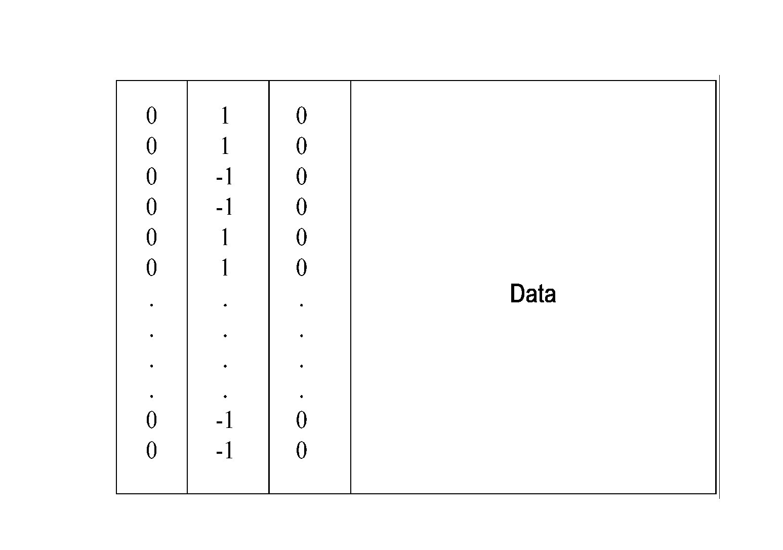
[0043]Referring to FIG. 4, without loss of generality, the situation is selected where the interval is 1, i.e. the preamble elements are mapped to the subcarrier consecutively; where the sequence of the preamble elements takes a pseudo-random sequence weighted by a weighting factor of 1.

[0044]The advantage for using a pseudo-random sequence is that it will be convenient to de-correlate intrinsic interferences on different subcarriers at the receiving side, which is beneficial for the subsequent processing of filtering the intrinsic interferences.

[0045]The weighting factor may also be selected to be a relatively large coefficient related to pilot power enhancement, which helps to improve the signal-to-interference-plus-noise ratio on the pilot to thereby improve the channel estimation accuracy, e.g. using a value greater tha...

second embodiment

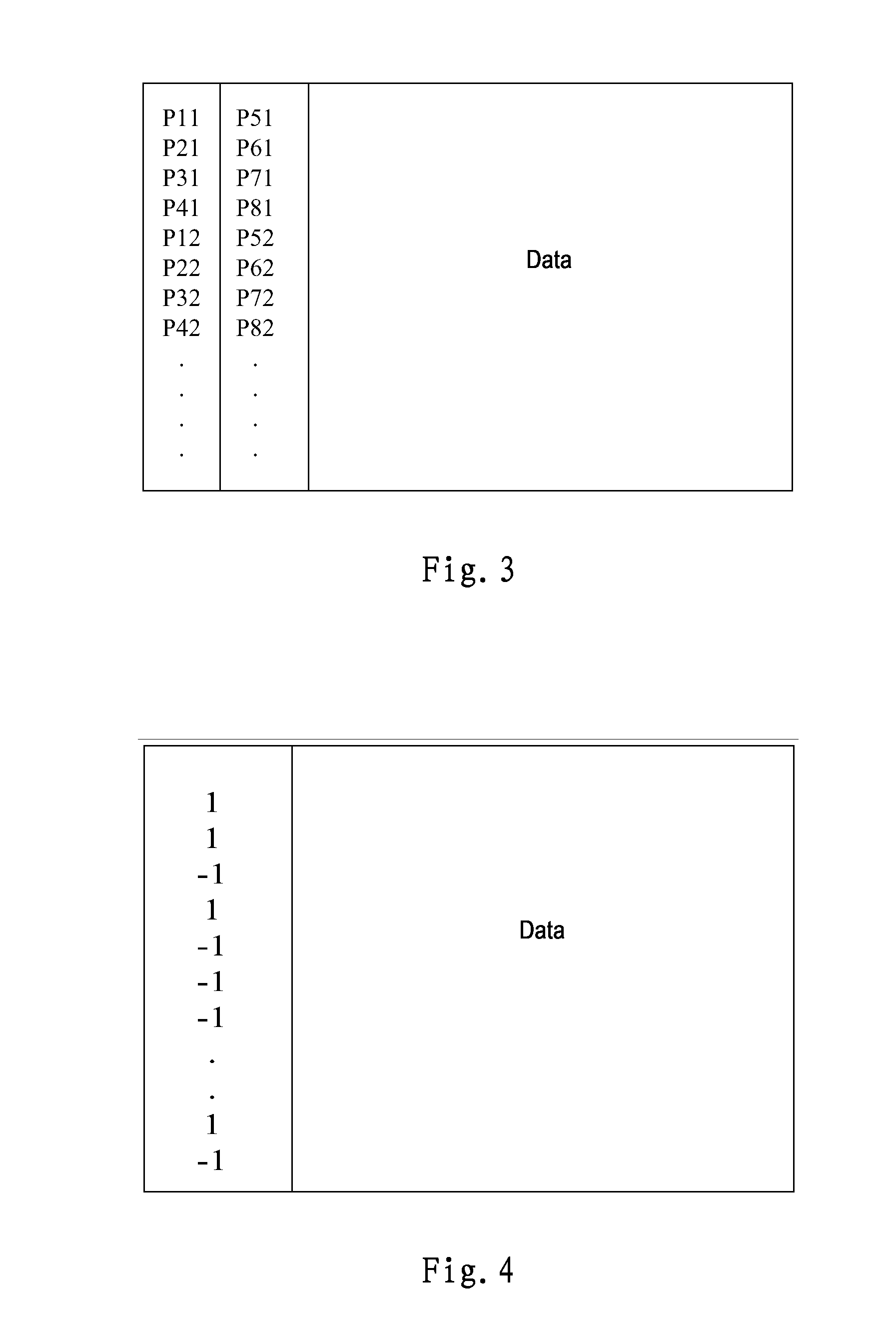
[0063]In the following embodiment, it is discussed that the preamble elements are mapped to the subcarriers unequally spaced.

[0064]Design of Pilot Preamble Symbols:

[0065]Referring to FIG. 7, the preamble elements are mapped to the subcarriers unequally spaced, wherein the sequence of the preamble elements takes a pseudo-random sequence weighted by a weighting factor of γp that represents a coefficient related to enhancement of the pilot power.

[0066]According to the above pilot preamble symbol design, the following method for transmitting signals is implemented in the transmitter of the FBMC system, as shown in FIG. 5.

[0067]S51. modulating data to obtain modulated data;

[0068]S52. obtaining a to-be-transmitted signal by framing the pilot preamble symbol as designed above with the modulated data; and

[0069]S53. transmitting the to-be-transmitted signal.

[0070]Channel Estimation Method:

[0071]Firstly, a signal model of the FBMC system is established as follows:

yi=hi(pi+jwi)+ni,i∈Sidx,

where...


PUM


Abstract

The present invention provides a method for transmitting signals in a transmitter of a filter band multi-carrier system, comprising steps of: modulating data to obtain modulated data; obtaining a to-be-transmitted signal by framing a pilot preamble symbol with the modulated data; transmitting the to-be-transmitted signal; the pilot preamble symbol consisting of preamble elements, wherein the pilot preamble symbol corresponding to each transmit antenna occupies one filter band multi-carrier modulation symbol. The present invention further provides an apparatus for implementing the method, and a method and apparatus for channel estimation corresponding to the method for transmitting signals.

Description

FIELD OF THE INVENTION[0001]The present invention relates to wireless communication technology field, and more particularly to a method and apparatus for signal transmission and corresponding channel estimation of a Filter Band Multi-Carrier (FBMC for short) system.BACKGROUND OF THE INVENTION[0002]Filter band multi-carrier modulation is a multi-carrier technology whose primary characteristic is that its subcarrier spectrum in the frequency domain may be designed and controlled flexibly such that it may properly suppress the out-of-band spectrum. The main manner for implementing FBMC is OQAM (offset QAM), that is, the real part and imaginary part of a complex constellation modulation symbol are separated so as to modulate respective pulse signals at a real and imaginary part interval in the time domain and frequency domain. Since the pulse signals have good energy concentration in both the time domain and the frequency domain, compared with the existing OFDM system, it may efficientl...

Claims


Application Information

Patent Timeline
Patent Type & Authority Applications(United States)
IPC IPC(8): H04L27/26H04L25/02
CPCH04L27/2613H04L25/0232H04L27/2698H04L27/264H04L5/0048H04L25/0228H04L27/2654H04L27/26416H04L5/00H04L27/26
Inventor LI, DONGCHEN, JINHUIWU, KEYING
Owner ALCATEL LUCENT SAS
Why Eureka
Try Eureka