Aerial optical fiber cables

a technology of optical fiber cables and ribbons, applied in the field of optical fiber cables, can solve the problems of difficult installation and handling, loose tubes or ribbons in the central core ribbon cables, and the bulky and heavy nature of traditional loose tube or central core optical cables, and achieve the effect of easy installation and handling in one operation, and high fiber counts

Active Publication Date: 2015-02-19
OFS FITEL LLC
View PDF1 Cites 15 Cited by
  • Summary
  • Abstract
  • Description
  • Claims
  • Application Information

AI Technical Summary

Benefits of technology

[0009]Thus there is a need for improved lightweight, compact, aerial cables with high fiber counts that can be installed easily in one operation.

Problems solved by technology

Traditional loose tube or central core optical cables are relatively bulky and heavy, and can be difficult to install and handle at closures, junction boxes, etc, where the cable jacket may need to be stripped for routing of fibers and cables.
Furthermore, if the cables are large and heavy it may be necessary to reinforce or replace existing telephone poles to support the added weight of the optical distribution cable.
Last, the tubes of a loose tube cable or ribbons in a central core ribbon cable can be difficult to route inside closures.
Loose buffer tubes tend to be stiff and hard to bend, while ribbons have a preferential bend that can make them difficult to route.
These stiff tubes, typically made out of a polymer like polybutylene terethphalate (PBT), are larger than the desired size of the cable units, and are prone to kinking permanently when handled.
Such practices add to the time and expense of deploying optical broadband distribution networks.
The softer tubes may meet the desired compact size of the units, but these tubes typically contain filling compound, which must be cleaned, and is an annoyance to installers.
When that occurs, and an installer attempts to remove cable sheath, the microsheath tube material may be inadvertently removed or torn thereby exposing the fibers and making it more difficult to determine which fiber is which.
Barrier tapes or other protective materials may be included in the cable sheath structure to help prevent damage to the microsheath tubes, but this adds to the cost and complexity of the cable.
However this is inefficient, as two different installation steps are required.
Also, there is a limit to the amount of fiber that can be installed in the conduit, as current commercially available ABFUs are limited to fiber counts of 12.

Method used


Image

  • Aerial optical fiber cables
  • Aerial optical fiber cables
  • Aerial optical fiber cables

Examples


Embodiment Construction

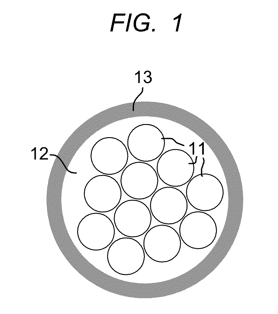
[0014]A typical multifiber tight buffer encasement unit of the invention is shown in FIG. 1. In FIG. 1, a twelve fiber embodiment is shown with the twelve optical fibers 11, encased and embedded in a soft acrylate matrix 12. As is well known, reference to an optical fiber means a glass fiber coated with a polymer protective coating. The elements in the figures are not drawn to scale. Surrounding and encasing the soft acrylate matrix is a relatively hard acrylate encasement layer 13. Together, the optical fibers, the acrylate matrix, and the acrylate encasement layer, comprise a round dual layer optical fiber tight buffer encasement. In this embodiment the multifiber tight buffer encasement contains 12 optical fibers, but may contain from 2-24 optical fibers. Multifiber tight buffer encasements with 4 to 12 optical fibers may be expected to be most common in commercial practice. The multifiber tight buffer encasement unit shown in FIG. 1 is described in greater detail in U.S. Pat. No...


PUM


Abstract

Described are cable designs adapted for aerial installations wherein the cable comprises a bundle of multifiber tight buffer encasement units, with a conformal thin skin containment layer surrounding the bundle. The multifiber tight buffer encasement units have an acrylate compliant inner layer that protects the fiber and minimizes stress transfer to the fiber; and a hard, tough acrylate outer layer that provides crush resistance. The thin skin containment layer provides cable integrity with a minimum of added size and weight. The thin skin containment layer encasement is encased in an outer protective jacket.

Description

RELATED APPLICATIONS[0001]This application claims the benefit of provisional application 61 / 606,033 filed Mar. 2, 2012, which is incorporated herein by reference.FIELD OF THE INVENTION[0002]This invention relates to optical fiber cables specially adapted for aerial installations.BACKGROUND OF THE INVENTION[0003](Parts of this background may or may not constitute prior art.)[0004]Aerial distribution cables are desirable for use in fiber-to-the-home, fiber-to-the-premises, or fiber-to-the-node broadband communications networks. These are especially worthwhile in construction of such high-speed networks in small towns and rural areas, where communications services are most economically provided using an existing aerial right of way.[0005]Traditional loose tube or central core optical cables are relatively bulky and heavy, and can be difficult to install and handle at closures, junction boxes, etc, where the cable jacket may need to be stripped for routing of fibers and cables. Furtherm...

Claims


Application Information

Patent Timeline
Patent Type & Authority Applications(United States)
IPC IPC(8): G02B6/44
CPCG02B6/441G02B6/4434G02B6/4436G02B6/4432G02B6/483
Inventor GIBBS, CARLTONGRAVESTON, MARK GPEDDER, JASONWEIMANN, PETER A
Owner OFS FITEL LLC
Why Eureka
Try Eureka