Method and device for improving efficiency of sponge oil absorption

a sponge oil and efficiency technology, applied in the direction of hydrogen separation using liquid contact, gaseous mixture working up, separation process, etc., can solve the problem of difficult absorption of lpg, and achieve the effect of improving the efficiency of sponge oil absorption

Active Publication Date: 2015-02-26
UOP LLC
View PDF2 Cites 10 Cited by
  • Summary
  • Abstract
  • Description
  • Claims
  • Application Information

AI Technical Summary

Benefits of technology

[0003]A first aspect of the invention is a method for improving efficiency of sponge absorption which includes providing cold flash drum liquid to an inlet of a cold stripper to produce a cold stripper net overhead vapor stream, and separately providing hot flash drum liquid to an inlet of a hot stripper to produce a hot stripper net overhead vapor stream. The cold stripper net overhead vapor and the hot stripper net overhead vapor are separately routed to a sponge absorber to recover a liquid petroleum gas output stream.
[0005]Still another aspect of the invention is a method for improving efficiency of sponge absorption including providing cold flash drum liquid to an inlet of a cold stripper to produce a cold stripper net overhead vapor stream rich in liquid petroleum gas, and separately providing hot flash drum liquid to an inlet of a hot stripper to produce a hot stripper net overhead vapor stream rich in hydrogen. The cold stripper net overhead vapor stream is routed to a first amine scrubber, and the hot stripper net overhead vapor stream is separately routed to a second amine scrubber separate from the first amine scrubber.

Problems solved by technology

However, the hydrogen content of the combined overhead vapor makes absorption of the LPG difficult.

Method used


Image

  • Method and device for improving efficiency of sponge oil absorption
  • Method and device for improving efficiency of sponge oil absorption
  • Method and device for improving efficiency of sponge oil absorption

Examples


Embodiment Construction

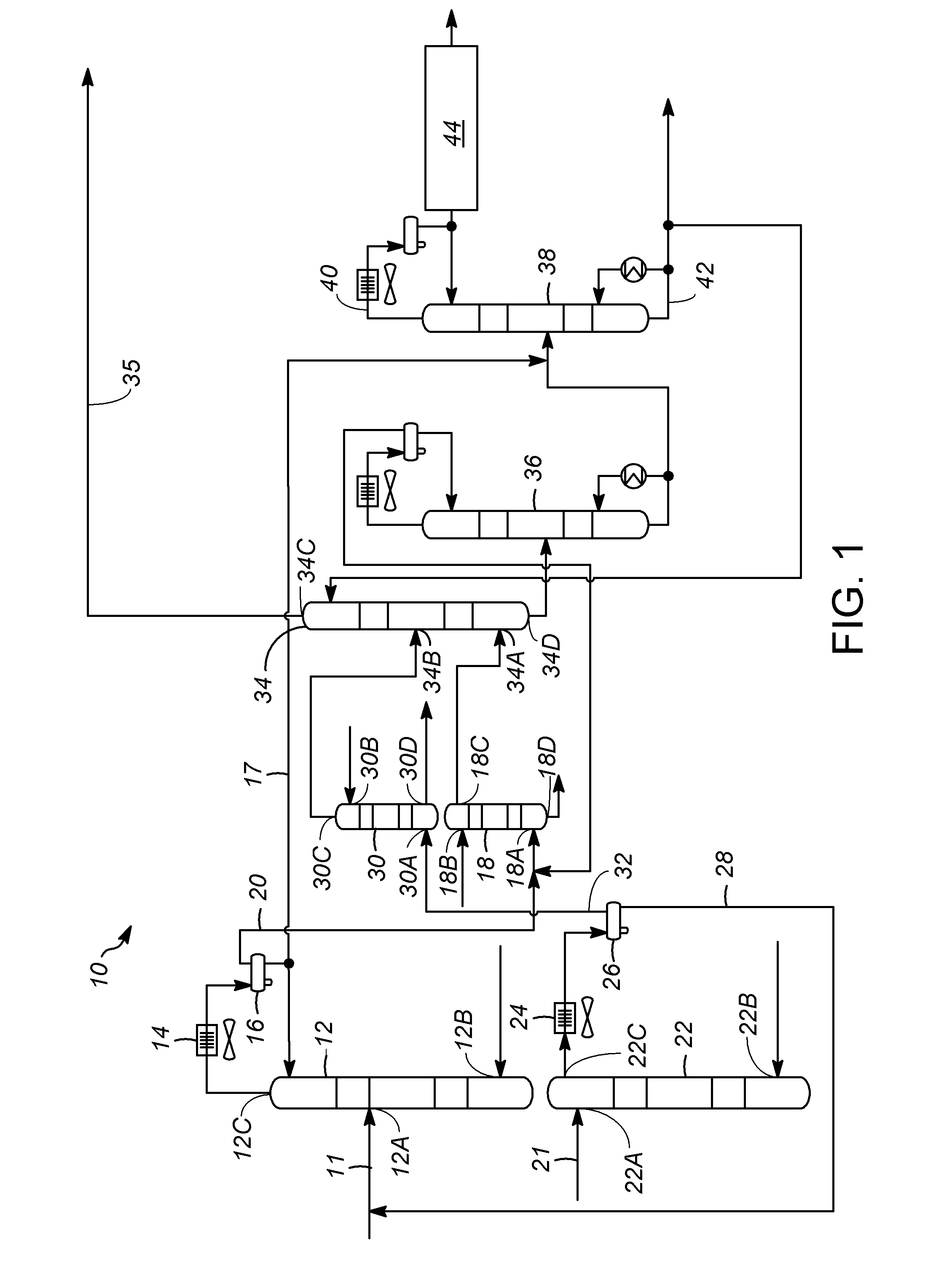
[0009]Based on various studies performed, it has been found that the presence of hydrogen in stripper net overhead vapor provided to a sponge absorber reduces the sponge absorber efficiency and requires large amount of sponge oil for absorption. Higher concentrations of hydrogen in the net overhead vapor stream result in higher sponge oil requirements for the desired LPG recovery.

[0010]When comparing the composition of cold flash drum liquid and hot flash drum liquid, the ratio of LPG and hydrogen in the cold flash drum liquid and hot flash drum liquid varies significantly. In particular, of the total LPG present in both the cold flash drum and hot flash drum liquid stream, about 70-90% of the LPG is present in the cold flash drum liquid, while only about 10-30% is present in the hot flash drum liquid. Conversely, of the hydrogen present in the combined feed (i.e. cold flash drum liquid and hot flash drum liquid) about 20-35% of the hydrogen is present in the cold flash drum liquid,...


PUM

PropertyMeasurementUnit
temperatureaaaaaaaaaa
concentrationsaaaaaaaaaa
pressureaaaaaaaaaa

Abstract

A method for improving efficiency of sponge absorption includes providing cold flash drum liquid to an inlet of a cold stripper to produce a cold stripper net overhead vapor stream rich in liquid petroleum gas, and separately providing hot flash drum liquid to an inlet of a hot stripper to produce a hot stripper net overhead vapor stream rich in hydrogen. The cold stripper net overhead vapor stream and the hot stripper net overhead vapor stream are separately routed to a sponge absorber to recover a liquid petroleum gas output stream using sponge oil. In particular, the cold stripper net overhead vapor stream and the hot stripper net overhead vapor stream are separately routed to the sponge absorber at different tray locations

Description

BACKGROUND OF THE INVENTION[0001]In conventional liquid petroleum gas (LPG) recovery maximization flow schemes in the hydrocracking technology, a large amount of sponge oil is required relative to the level of LPG recovered. In conventional LPG recovery process with a single stripper design or with a two stripper design (where hot stripper vapor may be fed to the cold stripper), a combined net overhead vapor from the one or more strippers is routed to a sponge absorber through an amine scrubber. However, the hydrogen content of the combined overhead vapor makes absorption of the LPG difficult.[0002]Accordingly, there is a need for a method to more efficiently absorb LPG from the hot stripper and cold stripper net overhead vapors.SUMMARY OF THE INVENTION[0003]A first aspect of the invention is a method for improving efficiency of sponge absorption which includes providing cold flash drum liquid to an inlet of a cold stripper to produce a cold stripper net overhead vapor stream, and s...

Claims


Application Information

Patent Timeline
Patent Type & Authority Applications(United States)
IPC IPC(8): C10G5/04
CPCC10G5/04C01B3/52C01B2203/0415C10G7/02C10G70/06C10G2400/28C10L3/12B01D53/14B01D53/96C10G2400/26
Inventor LADKAT, KIRANTIWARI, NEERAJ
Owner UOP LLC
Why Eureka
Try Eureka