Three-dimensional scanner

a three-dimensional scanner and scanner technology, applied in the field of scanners, can solve the problems of ineffective reduction of the cost the complicated image processing of the 3d scanner, and achieve the effects of low cost, simple component configuration, and high building efficiency

Active Publication Date: 2015-02-26
XYZPRINTING +2
View PDF23 Cites 26 Cited by
  • Summary
  • Abstract
  • Description
  • Claims
  • Application Information

AI Technical Summary

Benefits of technology

[0008]Accordingly, the invention is directed to a three-dimensional (3D) scanner, which has a simple component configuration, a higher efficiency in building of a digital 3D model and low cost.
[0011]According to the above descriptions, the 3D object is disposed on the rotary platform of the 3D scanner, and when the 3D object is rotated, the light source irradiates the 3D object to project the shadow of the 3D object onto the screen, or a collimated light source irradiates the 3D object to directly form a light contour on the surface of the 3D object to obtain contours of the 3D object from different angles, and the image capturing unit is used to capture the contour images of different angles, and then the processing unit is used to build a digital 3D model related to the 3D object according to the contour images. In this way, since the processing unit is only required to process the contour information of the 3D object, a loading of the processing unit in performing image processing and calculation is greatly mitigated, and efficiency for the 3D scanner building the digital 3D model is improved. Moreover, component configuration of the 3D scanner is rather simple, so that a production cost is reduced.

Problems solved by technology

However, such 3D scanner is complicated in image processing and calculation for building a digital 3D model, and a cost thereof cannot be effectively reduced.

Method used


Image

  • Three-dimensional scanner
  • Three-dimensional scanner
  • Three-dimensional scanner

Examples


Embodiment Construction

[0020]The present invention will now be described more fully with reference to the accompanying drawings, in which exemplary embodiments of the invention are shown. The terms used herein such as “above”, “below”, “front”, “back”, “left” and “right” are for the purpose of describing directions in the figures only and are not intended to be limiting of the invention. Moreover, in the following embodiments, the same or similar reference numbers denote the same or like components.

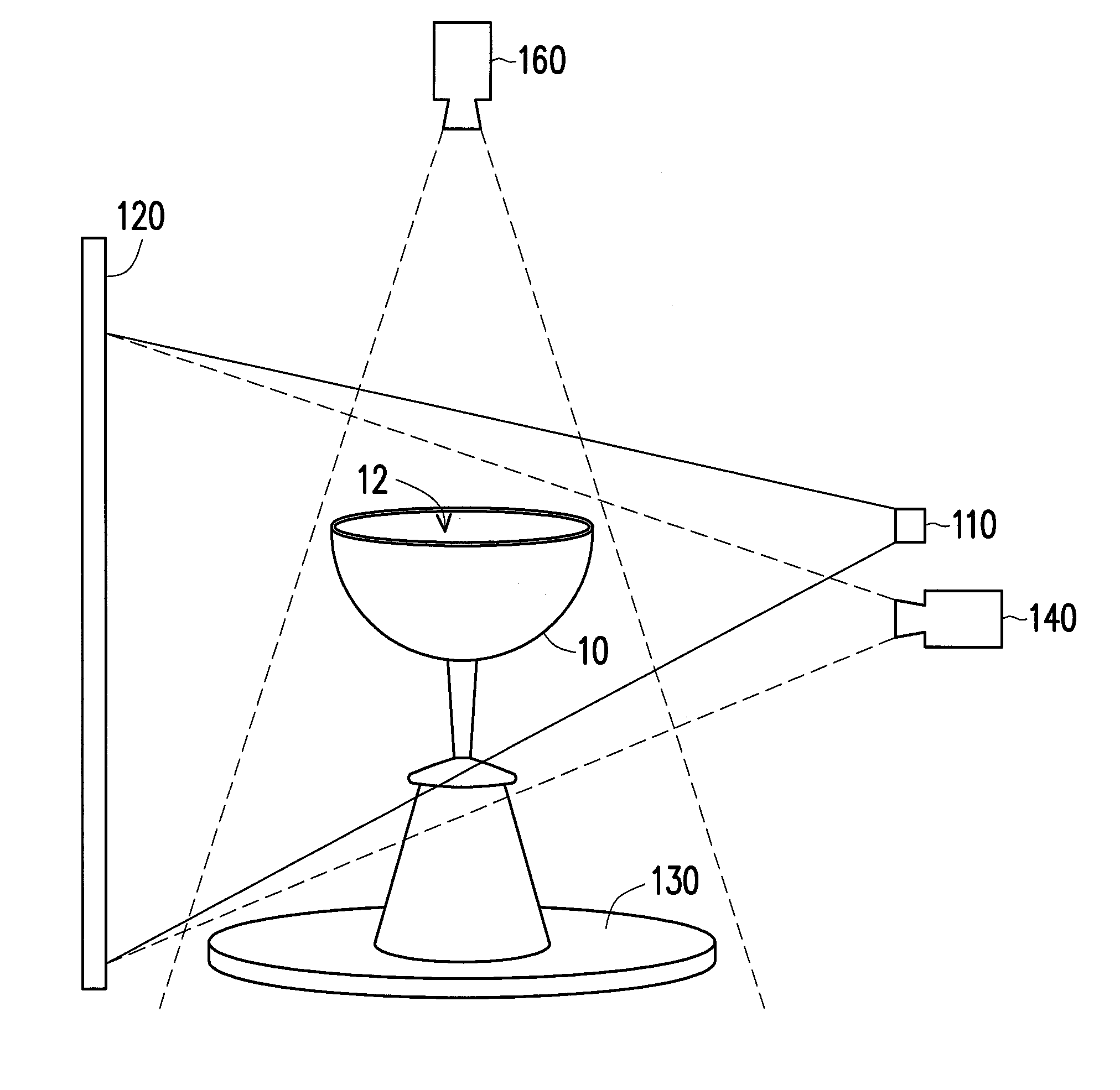
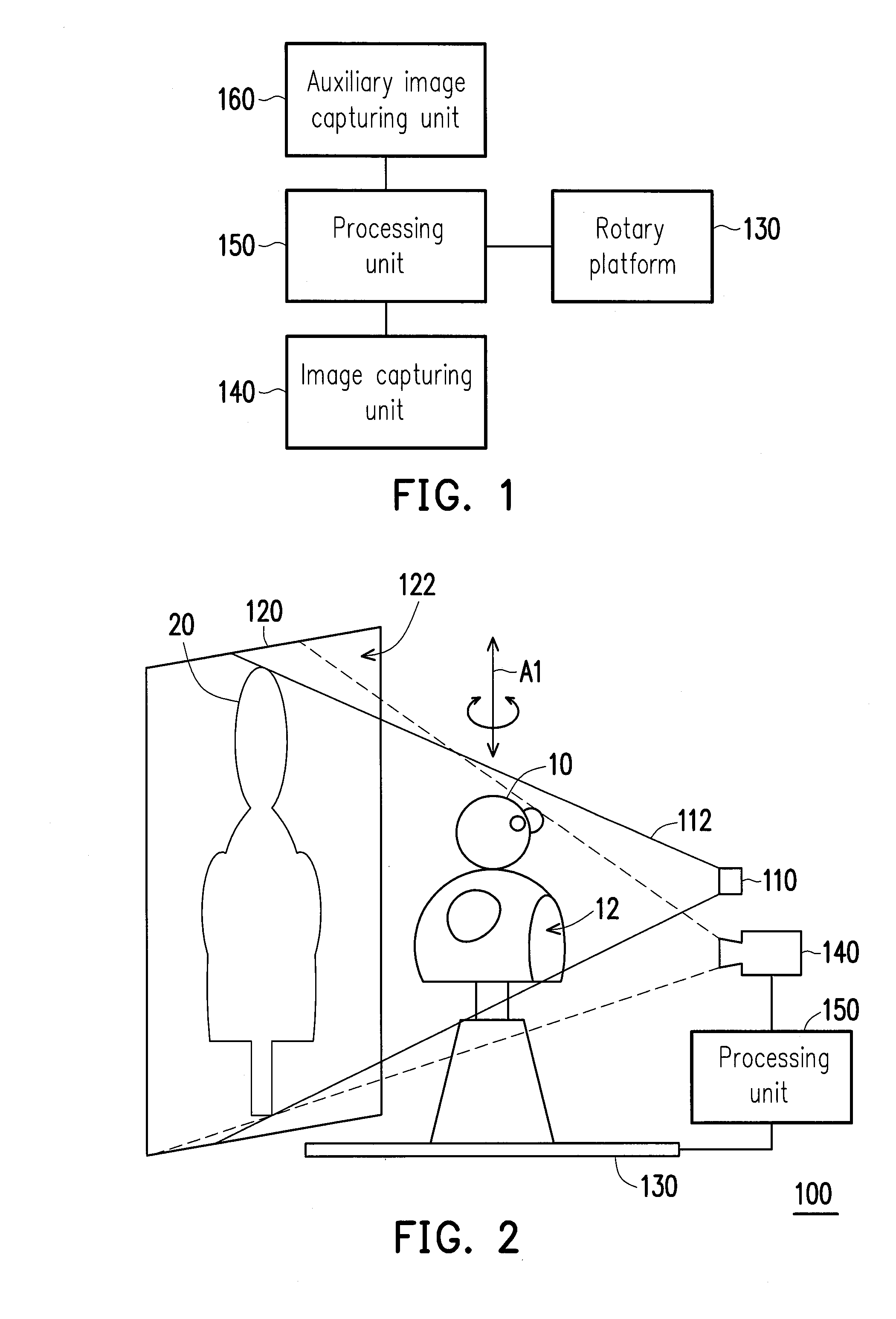
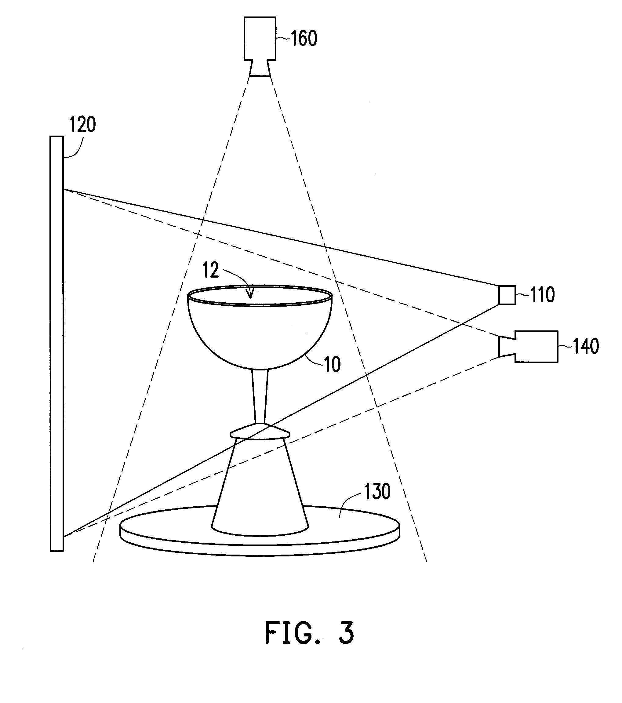
[0021]FIG. 1 is a partial block schematic diagram of a three-dimensional (3D) scanner according to an embodiment of the invention. FIG. 2 is a schematic diagram of a 3D scanner according to an embodiment of the invention. Referring to FIG. 1 and FIG. 2, in the present embodiment, the 3D scanner 100 performs a 3D model construction on a 3D object 10 to build a digital 3D model related to the 3D object 10. The 3D scanner 100 is, for example, coupled to a 3D printing apparatus, and the 3D printing apparatus reads ...


PUM


Abstract

A three-dimensional (3D) scanner including a light-source module, a screen, a rotary platform, an image capturing unit and a process unit is provided. The light source module is configured to emit a beam. The screen disposed on a transmission path of the beam has a projection surface facing the light source module. The rotary platform carrying a 3D object is disposed between the light source module and the screen. The 3D object is rotated to a plurality of object orientations about a rotating axis to form a plurality of object shadows on the projection surface. The image capturing unit is configured to capture the object shadows from the projection surface to obtain a plurality of object contour images. The process unit is configured to read and process the object contour images to build the digital 3D model related to the 3D object according to the object contour images.

Description

CROSS-REFERENCE TO RELATED APPLICATION[0001]This application claims the priority benefits of U.S. provisional application Ser. No. 61 / 869,079, filed on Aug. 23, 2013 and Taiwan application serial no. 102137783, filed on Oct. 18, 2013. The entirety of each of the above-mentioned patent applications is hereby incorporated by reference herein and made a part of this specification.BACKGROUND[0002]1. Technical Field[0003]The invention relates to a scanner. Particularly, the invention relates to a three-dimensional scanner.[0004]2. Related Art[0005]Along with progress of computer technology and development of multimedia technology, computers have gradually become indispensable tools in people's daily life, and rapid development of image processing technique leads to progress of computer peripheral image processors, for example, three-dimensional (3D) scanners.[0006]Generally, a 3D scanner is an instrument used for detecting and analysing shapes (geometric structures), and appearance infor...

Claims


Application Information

Patent Timeline
Patent Type & Authority Applications(United States)
IPC IPC(8): H04N13/02H04N13/221
CPCH04N13/0275G06T17/00H04N13/221G01B11/2522G01B11/2545H04N13/254
Inventor LEE, YANG-TEHHO, KWAN
Owner XYZPRINTING
Why Eureka
Try Eureka