Porous spacers, instruments, and methods for foot and ankle fusion

a technology of porous spacers and fusion joints, applied in the field of foot and ankle fusion, can solve the problems of time-consuming and difficult to reproduce custom shaping, and limited strength of bone grafts

Active Publication Date: 2015-02-26
ZIMMER INC
View PDF1 Cites 47 Cited by
  • Summary
  • Abstract
  • Description
  • Claims
  • Application Information

AI Technical Summary

Benefits of technology

[0033]In Example 19, a method for placing a bone implant or a provisional bone implant, comprises anchoring a resection frame to bone, the resection frame including an opening through which the bone implant or the provisional bone implant can pass; positioning a resection guide over the opening in the resection frame, the positioning blocking passage of the bone implant or the provisional bone implant through the opening in the resection frame while allowing passage of a bone cutting element through the resection guide and through the opening in the resection frame to cut underlying bone; creating a space for the bone implant or the provisional bone implant which includes passing a bone cutting element through a first cutting slot in the resection guide and through the opening in the resection frame and into underlying bone; repositioning the resection guide with respect to the opening in the resection frame such that the bone implant or the provisional bone implant can be passed through the opening in the resection frame; and passing the bone implant or the provisional bone implant through the opening in the resection frame and into the space.

Problems solved by technology

However, bone grafts have limited strength.
Because the ankle or foot must support a patient's body weight, the bone graft may become physically overloaded when implanted in this part of a patient's body.
Also, bone grafts may require intra-operative, custom shaping, which is time consuming and not readily reproducible.

Method used


Image

  • Porous spacers, instruments, and methods for foot and ankle fusion
  • Porous spacers, instruments, and methods for foot and ankle fusion
  • Porous spacers, instruments, and methods for foot and ankle fusion

Examples


Embodiment Construction

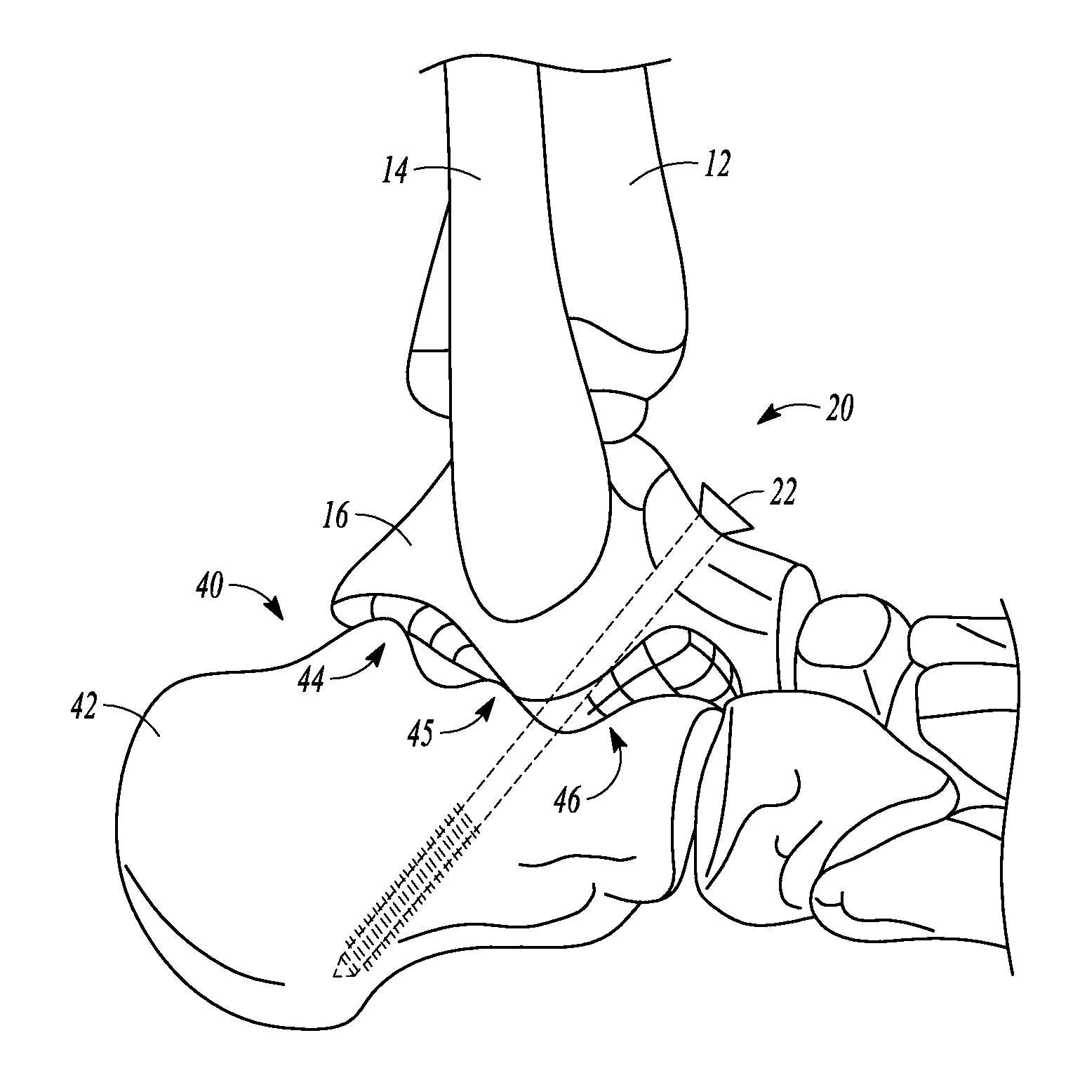
[0085]The present disclosure relates to spacers for foot and ankle fusion. Each fusion spacer is anatomically shaped for implantation in a particular anatomic location of the foot or ankle Each spacer shape may be available in different sizes (e.g., different anterior-posterior dimensions, different medial-lateral dimensions, different superior-inferior dimensions) to accommodate a variety of different patients.

1. Highly Porous Construction

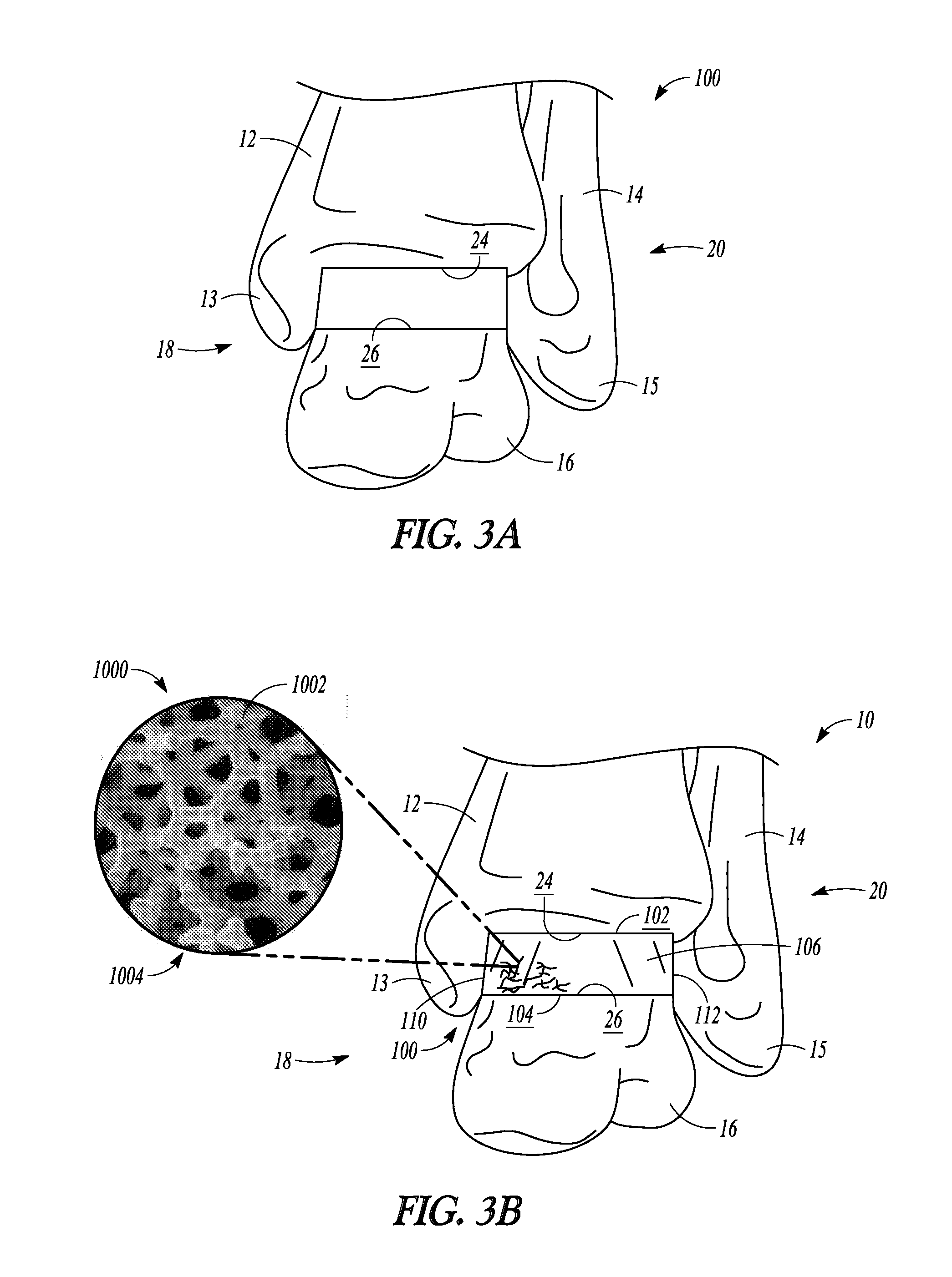
[0086]According to an exemplary embodiment of the present disclosure, the fusion spacers of the present disclosure are constructed of a highly porous biomaterial. A highly porous biomaterial is useful as a bone substitute and as cell and tissue receptive material. A highly porous biomaterial may have a porosity as low as 55%, 65%, or 75% or as high as 80%, 85%, or 90%.

[0087]An example of such a material is produced using Trabecular Metal™ Technology generally available from Zimmer, Inc., of Warsaw, Ind. Trabecular Metal™ is a trademark of Zimmer, ...


PUM


Abstract

Porous spacers (100) are provided for foot and ankle fusion. The porous spacers disclosed herein may be implanted between separate bones of a joint or between two segments of a single bone following an osteotomy procedure. Such spacers may be used in conjunction with an ankle resection system which includes a resection frame (150) and a resection guide (170). The resection frame can be anchored to the distal tibia and / or the talus and provides an opening (155) through which a bone cutting element can pass for cutting underlying bone. The resection guide can include one or more cutting slots (169, 171, 172) and the resection guide can be coupled to the resection frame with the one or more cutting slots positioned over the opening in the resection frame so that the bone cutting element can pass through the one or more cutting slots and through the opening in the resection frame for cutting the distal tibia and / or the talus.

Description

CLAIM OF PRIORITY[0001]This application claims the benefit of U.S. Provisional Patent Application Ser. No. 61 / 644,214, filed on May 8, 2012, which is incorporated by reference herein in its entirety.FIELD OF THE DISCLOSURE[0002]The present disclosure relates to foot and ankle fusion. More particularly, the present disclosure relates to porous spacers for foot and ankle fusion, and to instruments and methods for performing the same.BACKGROUND OF THE DISCLOSURE[0003]Bone grafts are generally used for foot and ankle fusion procedures. However, bone grafts have limited strength. Because the ankle or foot must support a patient's body weight, the bone graft may become physically overloaded when implanted in this part of a patient's body. Also, bone grafts may require intra-operative, custom shaping, which is time consuming and not readily reproducible.SUMMARY[0004]The present disclosure provides, in certain aspects, porous spacers for foot and ankle fusion. The porous spacers disclosed h...

Claims


Application Information

Patent Timeline
Patent Type & Authority Applications(United States)
IPC IPC(8): A61B17/17
CPCA61B2017/1775A61B17/1739A61B17/15A61B17/142A61B17/1775A61F2/4202
Inventor NEAL, DAVID J.MARKHAM, JOSEPHVALDERRABANO, VICTORCLARIDGE, RICHARDKIRCHNER, JOHN SHIRKDHARIA, MEHULZUBOK, RAYSTEBBINS, GREG
Owner ZIMMER INC
Why Eureka
Try Eureka