
Fitting a Parametric Curve using Maximum Curvature

Active Publication Date: 2015-03-05
ADOBE INC
View PDF4 Cites 16 Cited by
  • Summary
  • Abstract
  • Description
  • Claims
  • Application Information

AI Technical Summary

Benefits of technology

This patent describes a method for fitting a curve to a segment of data points using maximum curvature techniques. This allows for the creation of a smooth curve that matches the data points. The technique involves setting a point of maximum curvature for each segment of the curve and then responsively fitting subsequent data points into the curve so that they remain the points of maximum curvature. This technique can be implemented in hardware and can be used in various applications such as data analysis and mapping. Overall, this patent provides a technical solution for fitting curves to data points using maximum curvature techniques.

Problems solved by technology

However, conventional techniques that were utilized to perform curve fitting could depart from the expectations of users that avail themselves of the functionality.
Consequently, users of conventional techniques were often forced to manually correct the curve, which could be frustrating and inefficient.

Method used


Image

  • Fitting a Parametric Curve using Maximum Curvature
  • Fitting a Parametric Curve using Maximum Curvature
  • Fitting a Parametric Curve using Maximum Curvature

Examples


example environment

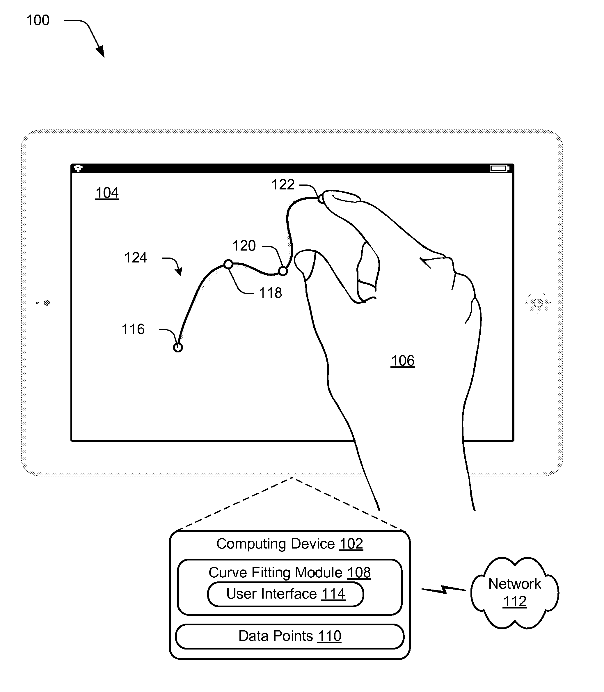
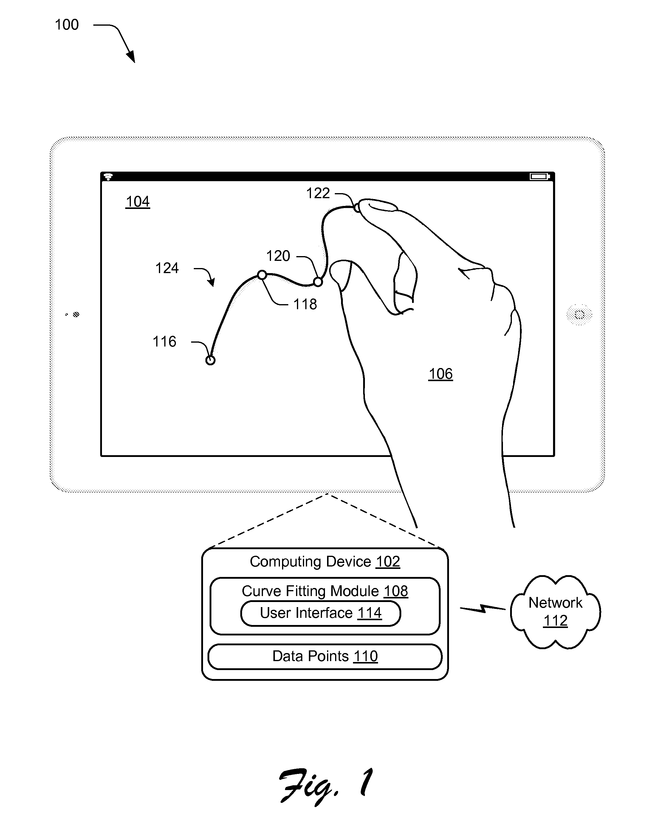
[0024]FIG. 1 is an illustration of an environment 100 in an example implementation that is operable to employ techniques described herein. The illustrated environment 100 includes a computing device 102, which may be configured in a variety of ways.

[0025]The computing device 102, for instance, may be configured as a desktop computer, a laptop computer, a mobile device (e.g., assuming a handheld configuration such as a tablet or mobile phone), and so forth. For example, as illustrated the computing device 102 is configured in a mobile configuration as a tablet that includes a display device 104 having touchscreen functionality that is configured to recognize touch inputs, such as those from a user's hand 106. Thus, the computing device 102 may range from full resource devices with substantial memory and processor resources (e.g., personal computers, game consoles) to a low-resource device with limited memory and / or processing resources (e.g., mobile devices). Additionally, although a...

example procedures

[0119]The following discussion describes curve techniques that may be implemented utilizing the previously described systems and devices. Aspects of each of the procedures may be implemented in hardware, firmware, or software, or a combination thereof. The procedures are shown as a set of blocks that specify operations performed by one or more devices and are not necessarily limited to the orders shown for performing the operations by the respective blocks. In portions of the following discussion, reference will be made to FIGS. 1-10.

[0120]FIG. 12 depicts a procedure 1200 in an example implementation in which a curve is fit and modified by leveraging maximum curvature techniques. A curve is fit to a plurality of segments of a plurality of data points, each of the segments including a first data point disposed between second and third data points, the first data point set as a point of maximum curvature for the segment (block 1202). As before, the curve fitting module 108 may obtain ...


PUM


Abstract

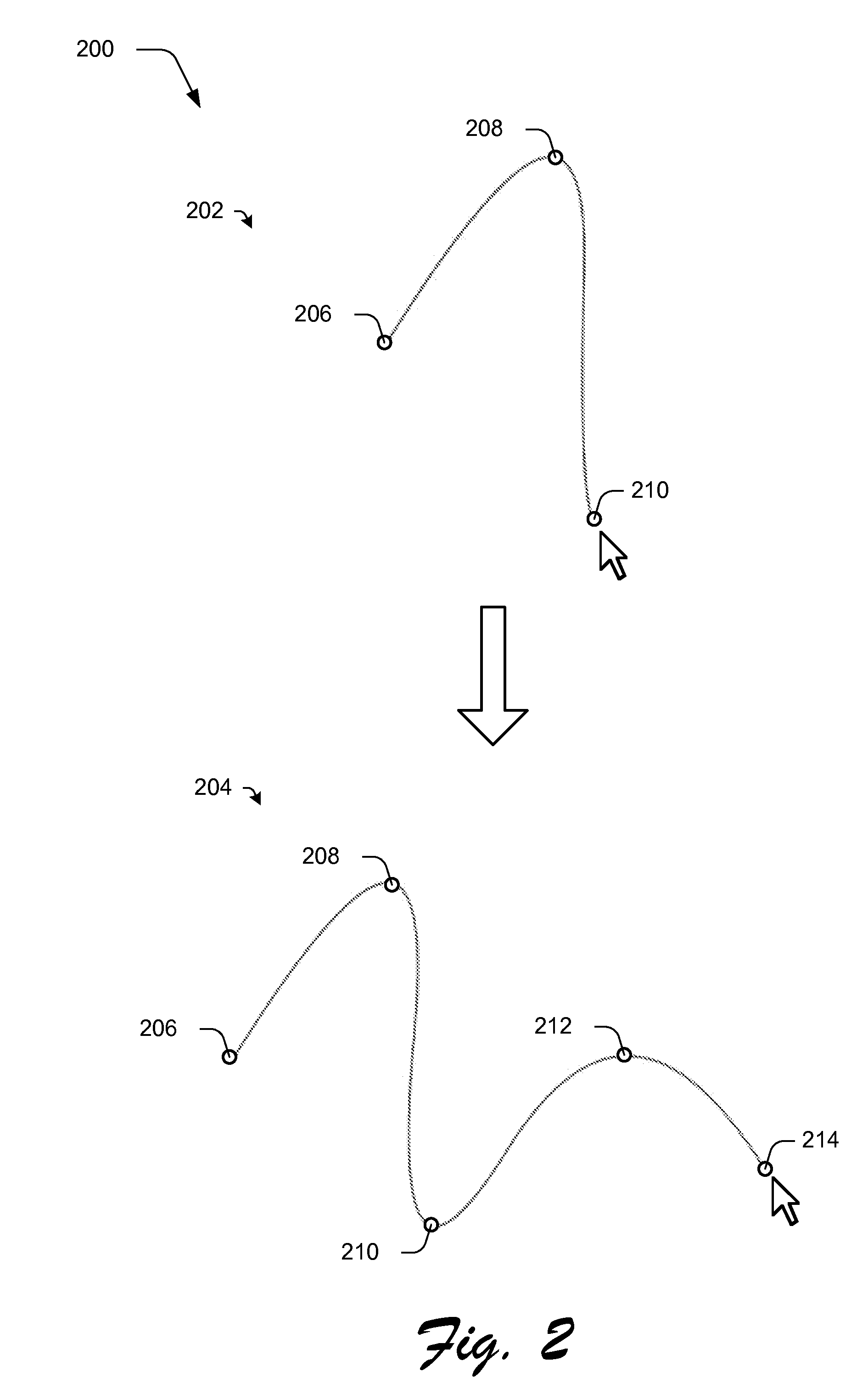
Parametric curve fitting using maximum curvature techniques are described. In one or more implementations, a parametric curve is fit to a segment of a plurality of data points that includes a first data point disposed between second and third data points by setting a point of maximum curvature for the segment of the curve at the first data point. A result of the fitting is output by the computing device.

Description

BACKGROUND[0001]Curve fitting refers to the fitting of a curve (e.g., path) between data points. This may be utilized for a variety of different purposes, such as to indicate correspondence of the data points, one to another, for spreadsheets, to draw animation paths, plotting temperatures, and so on.[0002]However, conventional techniques that were utilized to perform curve fitting could depart from the expectations of users that avail themselves of the functionality. For example, unexpected peaks, loops and so on may be observed in a curve fit using conventional techniques between the data points that do not “follow the flow” exhibited by the data points as expected by a user. Consequently, users of conventional techniques were often forced to manually correct the curve, which could be frustrating and inefficient.SUMMARY[0003]Parametric curve fitting is described that involves use of maximum curvature techniques. In one or more implementations, a curve is fit to a segment of a plur...

Claims


Application Information

Patent Timeline
IPC IPC(8): G06T11/20
CPCG06T11/203G06F3/0484G06F17/10G06T1/00G06T7/00G06T7/60G06T11/206
Inventor WILENSKY, GREGG D.CARR, NATHAN A.SCHILLER, STEPHEN N.
Owner ADOBE INC
Learn More