Backlight unit and liquid crystal display device including same

Inactive Publication Date: 2015-03-05
RES COOPERATION FOUND OF YEUNGNAM UNIV
View PDF0 Cites 79 Cited by
  • Summary
  • Abstract
  • Description
  • Claims
  • Application Information

AI Technical Summary

Benefits of technology

[0014]The backlight unit according to the present invention and the liquid crystal display including the backlight unit have the following effects.
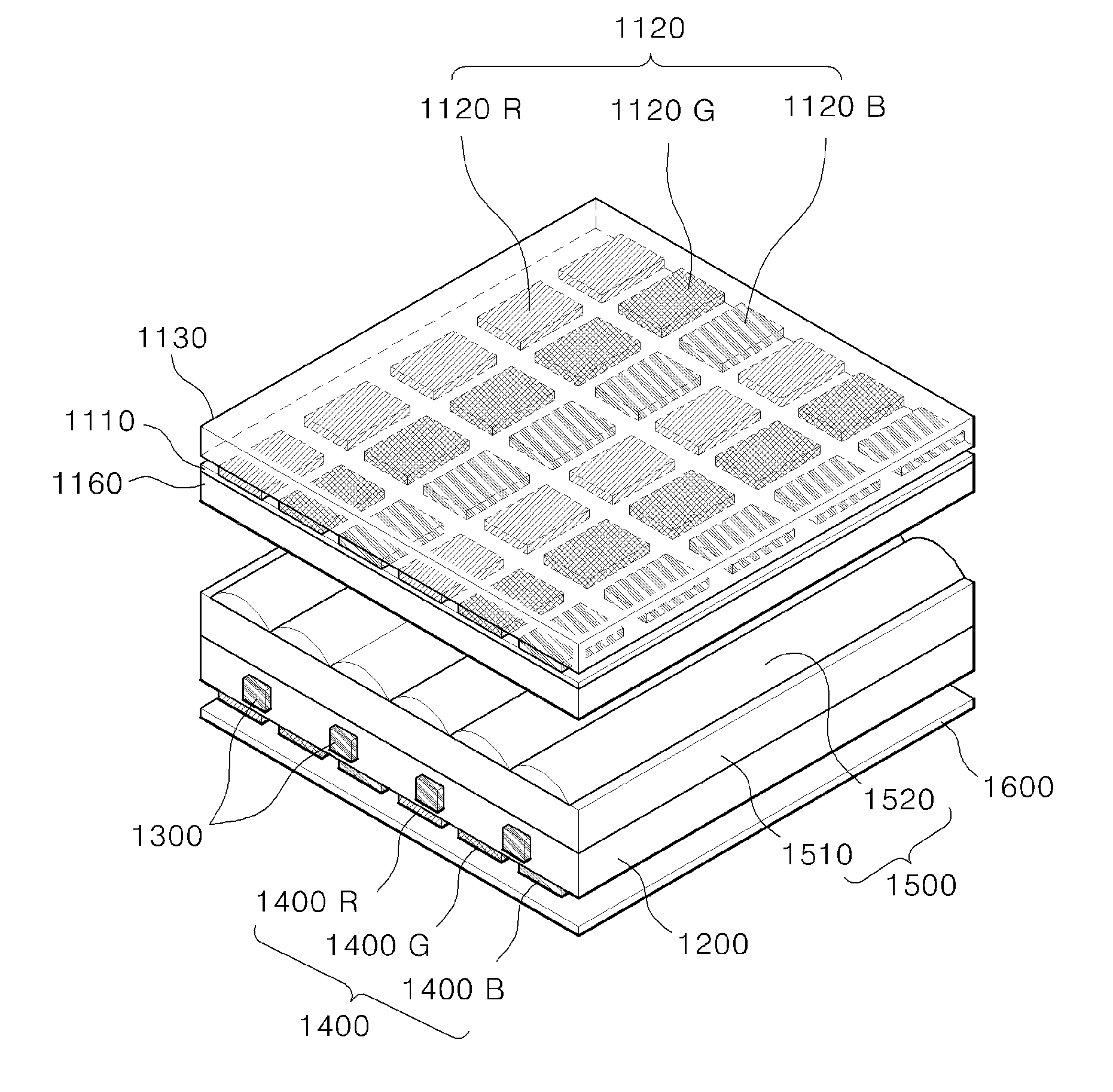
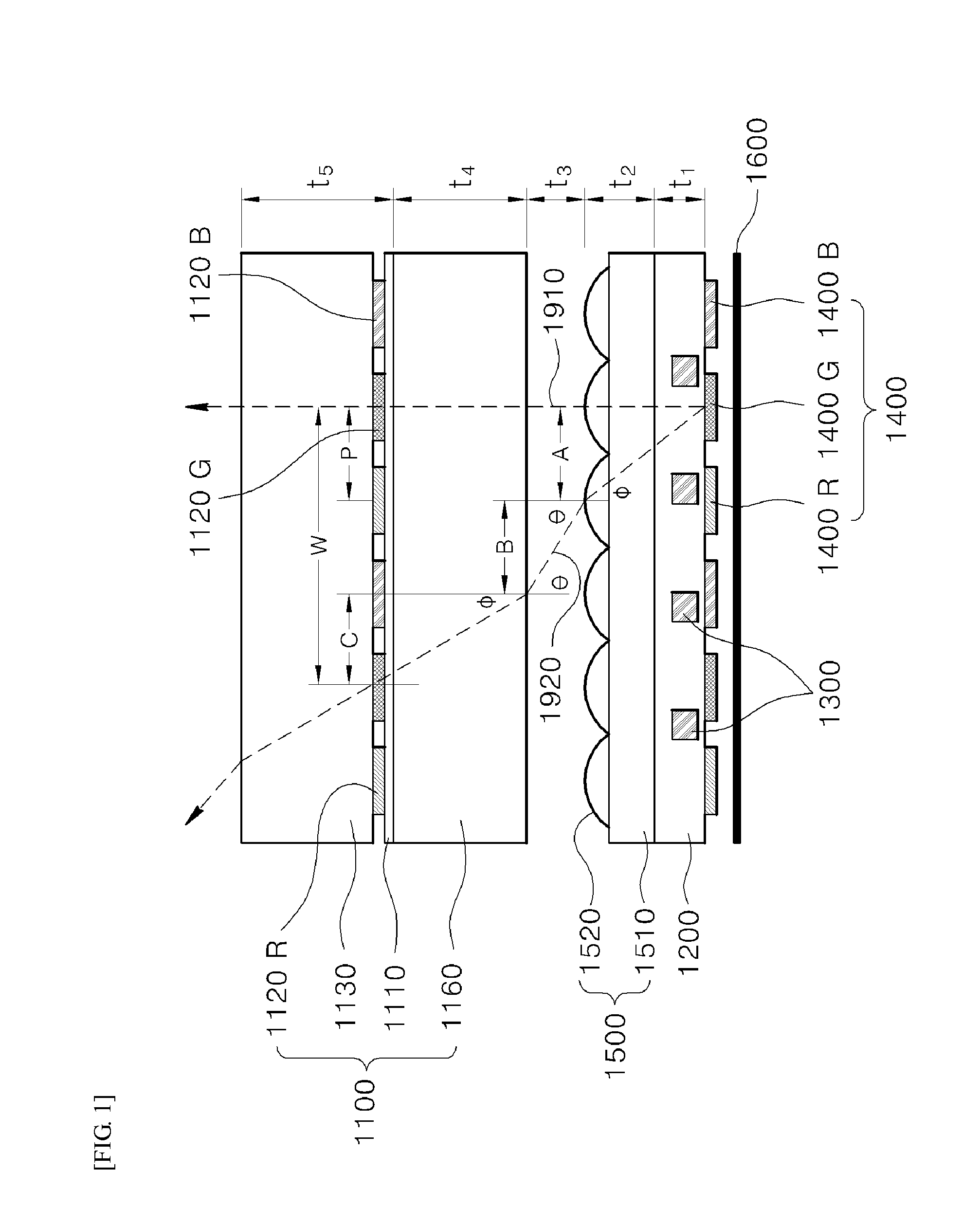
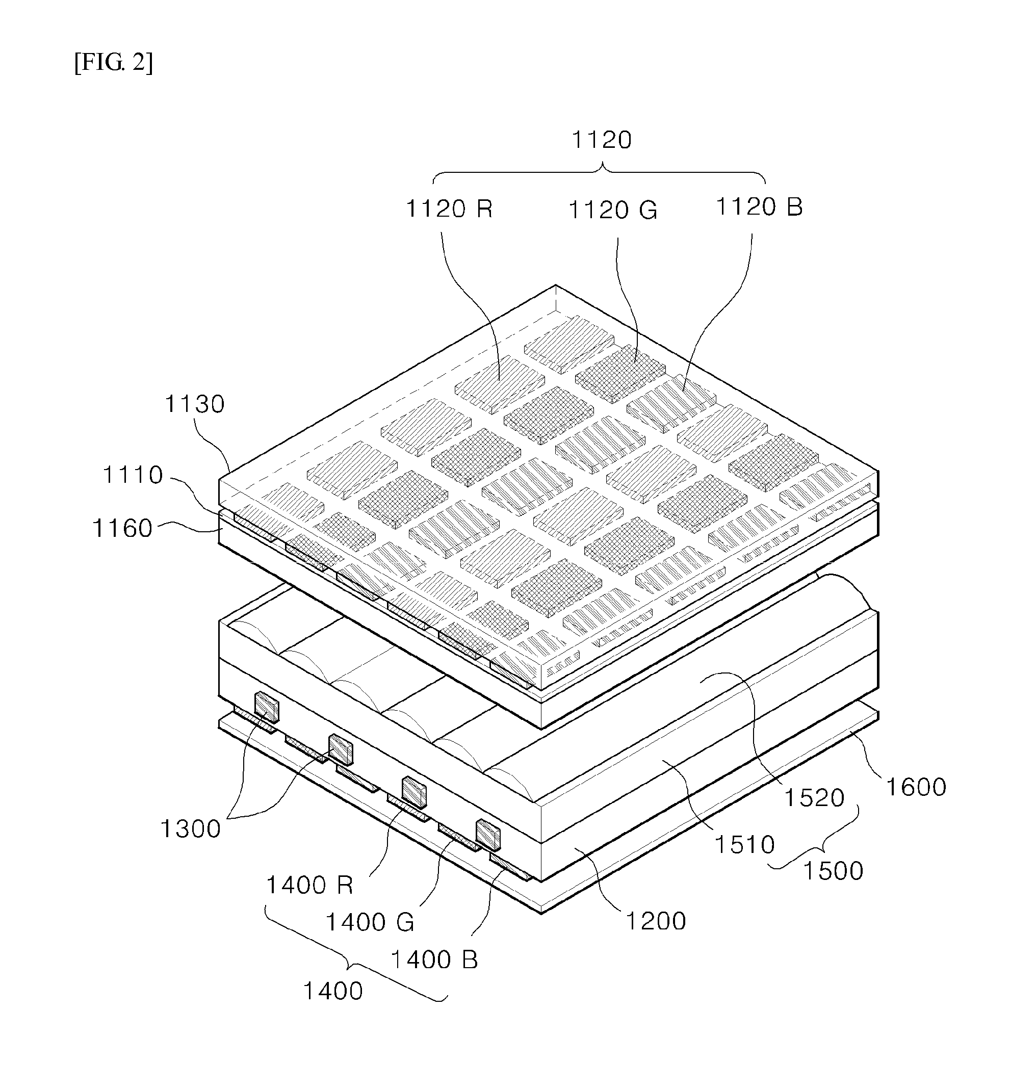
[0015]First, it is possible to improve light transmission efficiency of a liquid crystal liquid display by using a backlight unit that spreads red, green, and blue lights directly onto subpixels and color filters corresponding to red, green, and blue, respectively, using a three-color light source array corresponding to three of red, green, and blue light sources.
[0016]Second, since the lenticular lens array sheet and the color-matching sheet which have simple structures are used, they can be easily manufactured.
[0017]Third, since the R, G, B three color lights are produced by using R, G, B phosphors or R, G, B quantum dots which receive UV LED light and emit R, G, B light as t

Problems solved by technology

In LCDs of the related art, most of the power of white light from a backlight unit is lost by a polarizing sheet and a color filter on the front and rear of liquid crystal pixels, and the aperture ratio of liquid crystal pixels and only light of about 5 to 10% comes outside the liquid crystal panel, so there is a problem in that the optical energy efficiency of the LCDs is considerably low.
In particular, the color filter causes a large amount of loss of power of the LCDs by making the most loss of light, because its transmittance of light is only about 30%.
Although the FSC LCD technology has been considerably progressed by many researches, because it does not need subpixels and color filters and its light transmittance efficiency is improve

Method used


Image

  • Backlight unit and liquid crystal display device including same
  • Backlight unit and liquid crystal display device including same
  • Backlight unit and liquid crystal display device including same

Examples


first embodiment

[0061]FIG. 6 is an application example of the present invention of FIG. 5. The difference from FIG. 5 is that the three-color self-light emitting source array 2300 is disposed on a substrate and the lenticular lens array sheet 2500 is disposed between the liquid crystal panel 2100 and the three-color self-light emitting source array 2300, but the optical principle is the same as that in FIG. 5. The structure of FIG. 6 is the same as the application example of the first embodiment illustrated in FIG. 3, except that the three-color light source array 1400 (1400R, 1400G, 1400B) is replaced by the three-color self-light emitting source array 2300, so the color-matching condition is applied in the same way as the color-matching condition 2.

third embodiment

[0062]FIGS. 7 and 8 illustrate a third embodiment and a fourth embodiment of the present invention.

[0063]FIG. 7 illustrates a structure in which a color-matching sheet 3500 is disposed between a backlight unit having a light guide plate 3200 and a plurality of short wavelength light sources 3300, and a liquid crystal panel 3100. The short wavelength light sources 3300 for backlight are blue LEDs or ultraviolet LEDs.

[0064]The blue lights from the blue LEDs, which are the short wavelength light sources 3300, totally reflect in the light guide plate 3200 and then are diffused by a diffusion pattern 3210 under the light guide plate 3200 or reflected from a reflection sheet 3220 under the light guide plate 3200, such that their illuminance is made more uniform and the viewing angle is adjusted by a diffusion sheet 3600 or a light-concentrating sheet 3700, and then the lights travel into the color-matching sheet 3500. The structure of the light-concentrating sheet 3700 usually has the typ...


PUM


Abstract

Disclosed is a backlight unit that includes: a light guide plate that guides light, using internal total reflection; a plurality of short wavelength light sources that are disposed on a side of the light guide plate and radiate short wavelength lights into the light guide plate; a three-color light source array that is disposed on the bottom or the top of the light guide plate and includes a plurality of color conversion materials exciting the short wavelength lights from the short wavelength light sources into red or green or blue; and a lenticular lens array sheet that is disposed between the three-color light source array and the liquid crystal panel and refracts the three color lights emitted from the three-color light source array into the subpixels.

Description

TECHNICAL FIELD[0001]The present invention relates to a backlight unit (BLU) of a liquid crystal display, and more particularly, to a backlight unit capable of improving optical efficiency of a liquid crystal display and a liquid crystal display including the backlight unit.BACKGROUND ART[0002]In general, a liquid crystal display is composed of a liquid crystal panel converting various items of electric image information into video information, using a change in transmittance of a liquid crystal due to an applied voltage, and a backlight unit supplying light to the liquid crystal panel. A plurality of liquid crystal pixels in the liquid crystal panel is composed of R, G, and B subpixels that make red (R), green (G), and blue (B) images, respectively, and R, G, and B color filters are disposed on the fronts of the subpixels.[0003]In LCDs of the related art, most of the power of white light from a backlight unit is lost by a polarizing sheet and a color filter on the front and rear of...

Claims


Application Information

Patent Timeline
IPC IPC(8): G02F1/1335G02F1/017F21K99/00G02B3/00F21V8/00
CPCG02F1/133621G02B3/005G02B6/0055F21K9/56G02F2001/01791G02F1/133524G02F1/133603G02F1/01708G02F1/133617G02F1/133606G02B6/0026G02B6/003G02B6/0068G02F1/01791G02F1/133607G02F1/133614G02F1/1335
Inventor KWON, JIN HYUK
Owner RES COOPERATION FOUND OF YEUNGNAM UNIV
Why Eureka
Try Eureka