Discharge lamp and control of the same

a discharge tube and discharge tube technology, applied in the direction of transit tube circuit elements, cathode-ray/electron beam tube circuit elements, structural circuit elements, etc., can solve the problems of poor light transmission efficiency, insufficient discharge efficiency and stability of output intensity, and light loss, so as to increase the discharge efficiency, output intensity stability and transmission efficiency of the discharge tube

Inactive Publication Date: 2006-03-09
SEIKO EPSON CORP
View PDF7 Cites 0 Cited by
  • Summary
  • Abstract
  • Description
  • Claims
  • Application Information

AI Technical Summary

Benefits of technology

[0011] A first object of the present invention is to provide a technology to increase the discharge efficiency, output intensity stability and transmission efficiency of a discharge tube.

Problems solved by technology

The above conventional discharge tube may fluctuate in its discharge characteristics, and offers insufficient discharge efficiency and stability of output intensity.
Furthermore, as a result of the electrodes or the like residing in the light transmission path, the problems of light loss and poor light transmission efficiency may occur.
In addition, various problems arise due to the fact that the discharge lamp is a light source that repeatedly blinks on and off.
For example, where this type of discharge lamp is used in a display device such as a projector, flicker caused by interference between the light source illumination frequency and the display device drive frequency occurs.
Furthermore, where this type of discharge lamp that repeatedly blinks on and off is used as an illumination device, flicker caused by interference with the light source illumination frequency of a different light source in the area may occur.
Moreover, the discharge frequency may cause stress on the eyes and brain.
However, if DC voltage is impressed, the load on the electrodes becomes large, thereby shortening their life span.

Method used


Image

  • Discharge lamp and control of the same
  • Discharge lamp and control of the same
  • Discharge lamp and control of the same

Examples


first embodiment

A. First Embodiment

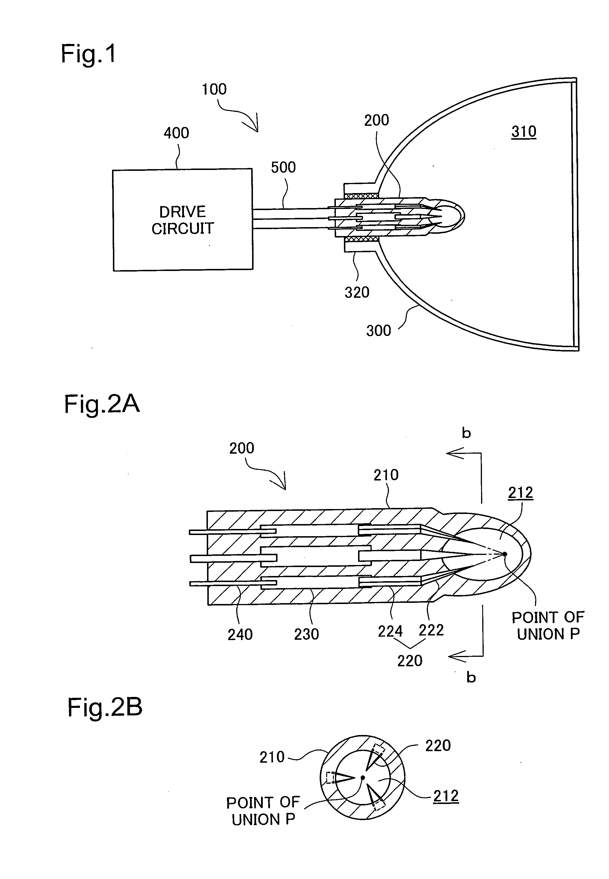
[0047]FIG. 1 is an explanatory drawing showing the basic construction of a discharge lamp having a discharge tube in a first embodiment of the present invention. The discharge lamp 100 includes a discharge tube 200, a reflecting case 300, a drive circuit 400 and a power supply line 500 that connects the discharge tube 200 and the drive circuit 400. The discharge tube 200 is secured to a base portion 320 of the reflecting case 300 such that the tip thereof protrudes inside a hollow space 310 of the reflecting case 300. The hollow space 310 of the reflecting case 300 contains nitrogen gas, for example.

[0048] The discharge lamp 100 is used as a projector light source, a vehicle headlight, an illuminating device or the like.

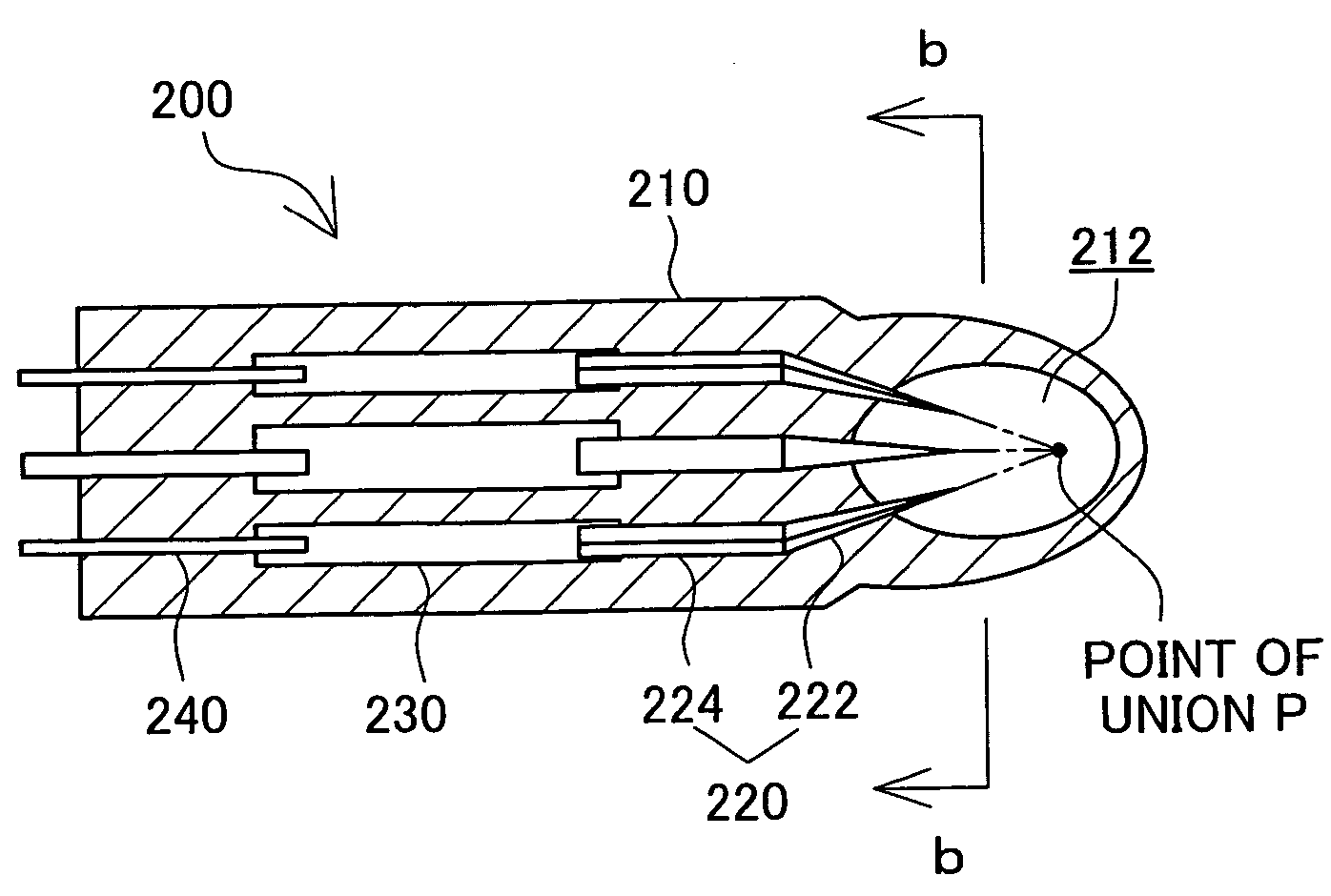
[0049]FIGS. 2A and 2B are explanatory drawings showing the detailed construction of the discharge tube in the first embodiment. FIG. 2A shows a horizontal cross-section of the discharge tube 200, while FIG. 2B shows a cross-sectional view cut alo...

second embodiment

B. Second Embodiment

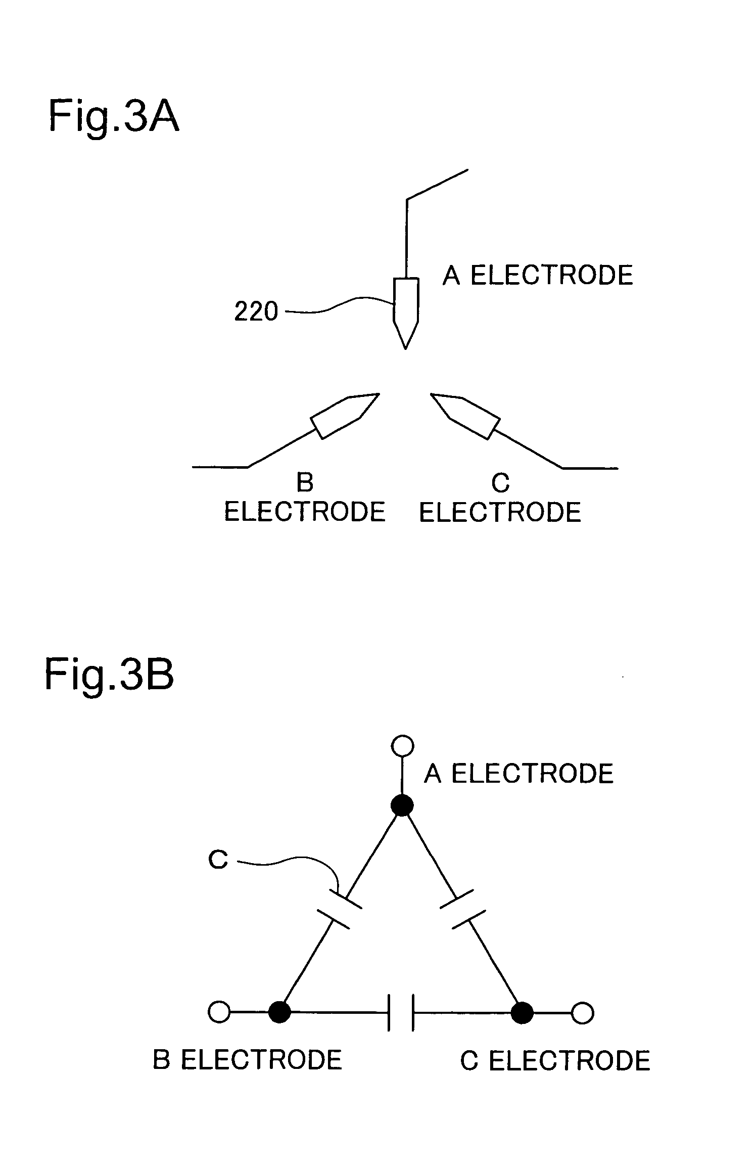
[0062]FIGS. 7A and 7B are conceptual drawings of electrodes of a discharge tube in a second embodiment of the present invention. The discharge tube 200 of the second embodiment differs from the first embodiment in that it is driven by a two-phase drive circuit. As a result, the discharge tube 200 in the second embodiment differs from the first embodiment shown in FIG. 3 in that it includes an A electrode, a B electrode and a COM electrode (for ‘common’). The three electrodes 220 are disposed in the manner shown in FIG. 7A, and are equivalent to an electric circuit in which the A and B electrodes are each connected to the COM electrode via capacity C as shown in FIG. 7B. The detailed constructions of the discharge lamp 100 in the second embodiment and of the discharge tube 200 in the second embodiment are identical to the equivalent constructions in the first embodiment shown in FIGS. 1 and 2.

[0063]FIG. 8 is an explanatory drawing showing the construction of a dr...

third embodiment

C. Third Embodiment

[0069]FIG. 10 is an explanatory drawing showing the basic construction of a liquid crystal projector as an embodiment of the projection-type image display device of the present invention. The liquid crystal projector 1010 includes a receiver 1020, an image processor 1030, a liquid crystal panel drive unit 1040, a liquid crystal panel 1050, a projection optical system 1060 that projects onto a screen SC transmitted light that passes through the liquid crystal panel 1050, and a CPU 1700. The liquid crystal projector 1010 further includes a discharge lamp 1600 that illuminates the liquid crystal panel 1050 and a discharge lamp controller 1000 that controls the discharge lamp 1600.

[0070] The receiver 1020 inputs image signals VS supplied from a personal computer or the like not shown and converts them to image data having a format that can be processed by the image processor 1030. The image processor 1030 carries out various types of image processing to the image dat...


PUM


Abstract

A discharge tube is driven by a multiple-phase drive circuit, and includes a discharge container having an internal discharge space and multiple electrodes that are secured to the discharge container and correspond to each phase of the multiple-phase drive circuit. The tips of the multiple electrodes protrude into the discharge space, and are oriented toward a predetermined single point of union. All of the electrodes located on one side of a virtual plane that includes the predetermined point of union. Furthermore, a discharge lamp having the discharge tube includes three electrodes, and electric discharge can take place between each pair of electrodes. When the discharge lamp is driven at maximum output, voltage is impressed to the three electrode terminals such that at least one of the voltages VeAB, VeBC, VeCA between the three electrode terminals will be in a discharge period.

Description

CROSS REFERENCE TO RELATED APPLICATIONS [0001] The present application claims the priority based on Japanese Patent Application No. 2004-262188 filed on September 9, 2004 and Japanese Patent Application No. 2005-72873 filed on March 15, 2005, the disclosures of which are hereby incorporated herein by reference in their entireties. BACKGROUND OF THE INVENTION [0002] 1. Field of the Invention [0003] The present invention relates to a discharge tube, and more particularly to a technology to drive a discharge tube efficiently and stably. The present invention further relates to the control of a discharge lamp. [0004] 2. Description of the Related Art [0005] A discharge lamp having a discharge tube is used as a light source for a projector or other device. This discharge tube may be driven by a single-phase power supply (e.g. JP06-325735A) or a multiple-phase power supply (e.g. JP64-86442A). [0006] A discharge lamp of the conventional art commonly has two electrodes. A discharge lamp con...

Claims


Application Information

Patent Timeline
Patent Type & Authority Applications(United States)
IPC IPC(8): H01K1/62
CPCH01J61/86H05B41/2881H05B41/2827
Inventor TAKEUCHI, KESATOSHI
Owner SEIKO EPSON CORP
Why Eureka
Try Eureka