Projector

a projector and projector technology, applied in the field of projectors, can solve the problems of uneven illumination of images, and achieve the effect of reducing the uneven illumination of images

Active Publication Date: 2015-03-05
SEIKO EPSON CORP
View PDF7 Cites 0 Cited by
  • Summary
  • Abstract
  • Description
  • Claims
  • Application Information

AI Technical Summary

Benefits of technology

[0007]An advantage of some aspects of the invention is to provide a projector capable of reducing illuminance unevenness of an image when tilt projection is performed.

Problems solved by technology

On the other hand, there is a problem in that, when the tilt projection is performed, an upper part of the image projected onto the screen is darker than a lower part thereof, and thus uneven illuminance occurs in the image.

Method used


Image

  • Projector
  • Projector
  • Projector

Examples


first embodiment

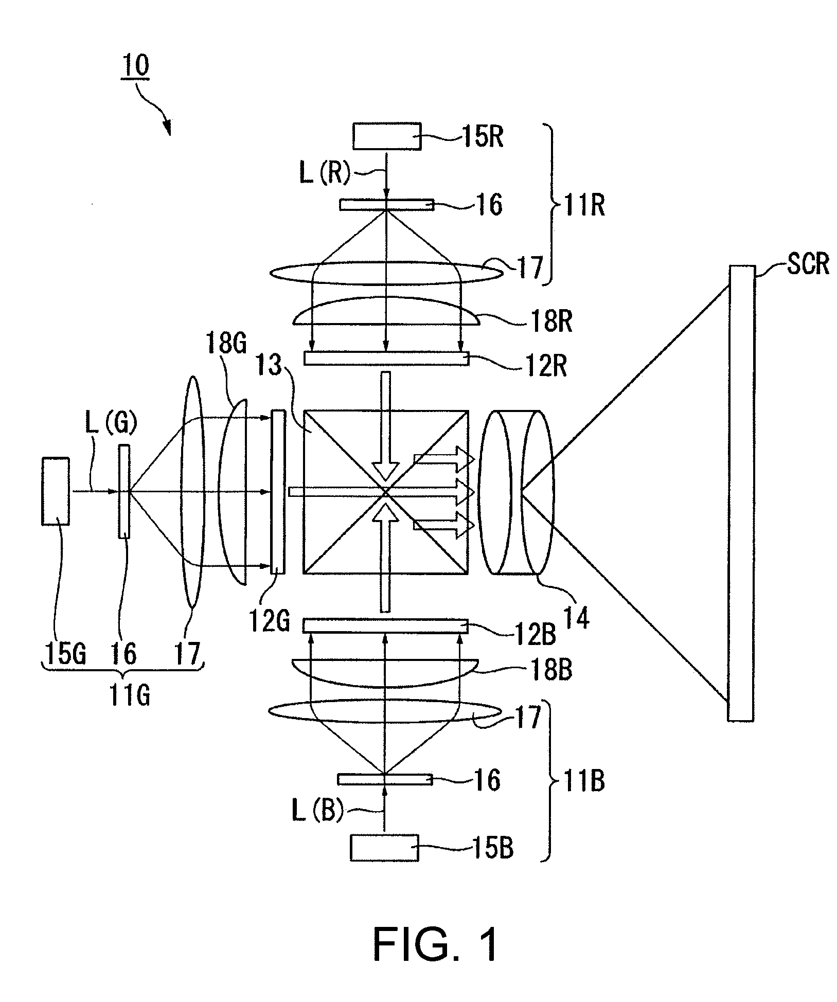
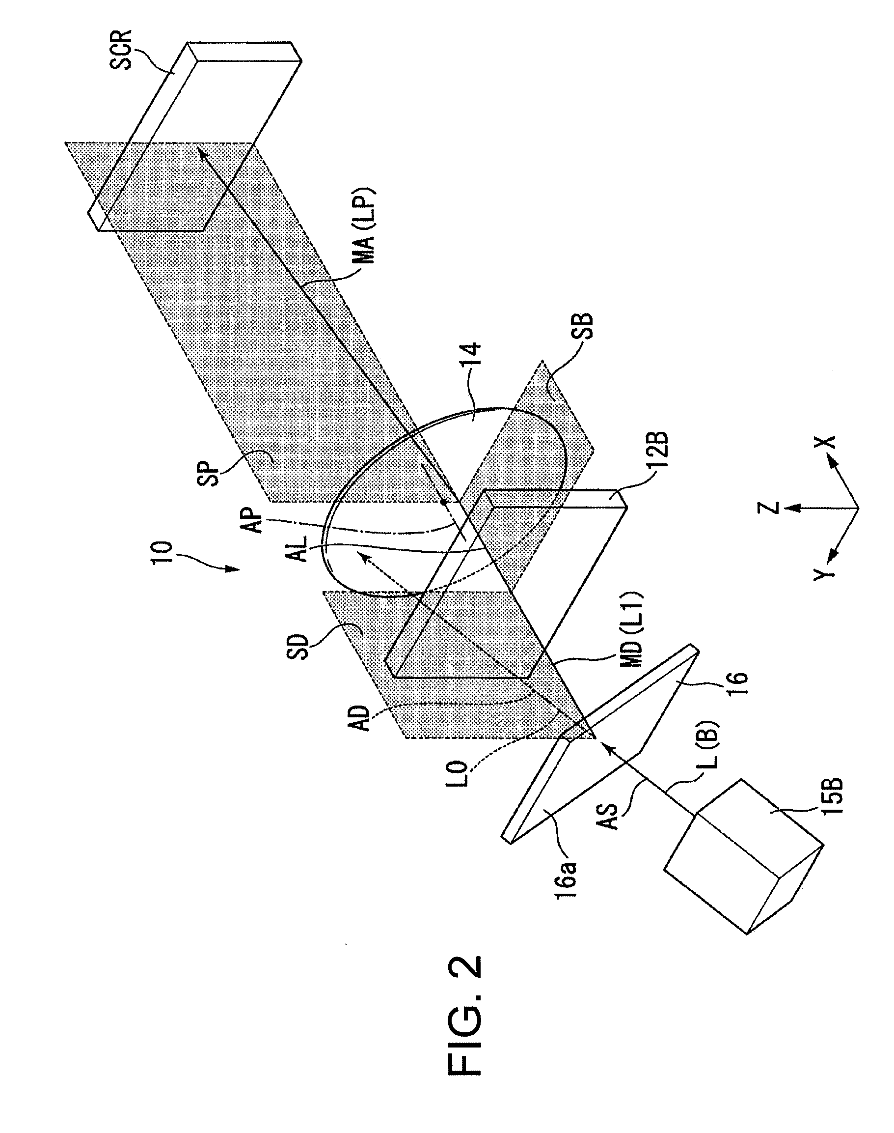
[0039]FIG. 1 is a schematic diagram illustrating a projector 10 of the present embodiment. FIG. 2 is a perspective view schematically illustrating a partial configuration of the projector 10. FIG. 3 is a side view schematically illustrating a partial configuration of the projector 10. In FIGS. 2 and 3, for description, some members are not illustrated as appropriate, and an arrangement relationship is also changed as appropriate.

[0040]In addition, in FIGS. 2 and 3, and FIGS. 4 and 6 to 10 described later, an XYZ coordinate system is set, and a positional relationship of each member is described with reference to the XYZ coordinate system. In this case, a vertical direction is set to a Z axis direction, a direction which is perpendicular to the Z axis direction and is also perpendicular to a surface of a light modulation device 12B (refer to FIG. 2) on which light is incident is set to an X axis direction, and a direction perpendicular to the X axis direction and the Z axis direction...

second embodiment

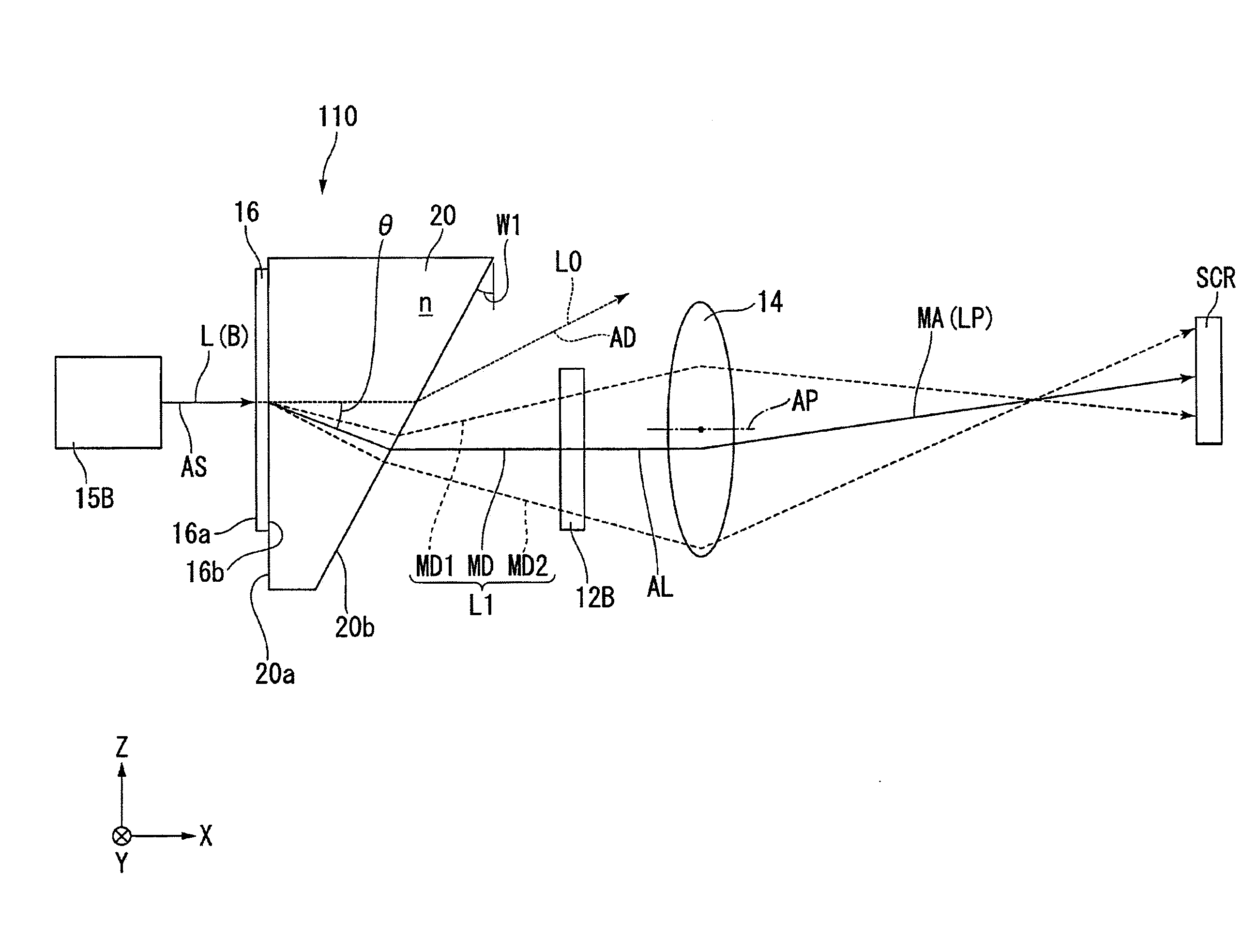
[0080]The present embodiment is different from the first embodiment in that an optical path conversion element 20 is provided.

[0081]In addition, the same constituent elements as those of the above-described embodiment are given the same reference numerals, and description thereof will be omitted in some cases.

[0082]FIG. 5 is a schematic diagram illustrating a projector 110 of the present embodiment. FIG. 6 is a perspective view schematically illustrating a partial configuration of the projector 110. FIG. 7 is a side view schematically illustrating a partial configuration of the projector 110. In FIGS. 6 and 7, for description, members are not illustrated as appropriate, and an arrangement relationship is also changed as appropriate.

[0083]The projector 110 of the present embodiment includes, as illustrated in FIG. 5, an illumination device 111R, an illumination device 111G, an illumination device 111B, a field lens 18R, a field lens 18G, a field lens 18B, a light modulation device 12...


PUM


Abstract

A projector includes a light source device, a diffraction element that converts light from the light source device into 0-th order light and diffracted light, a light modulation device that modulates the diffracted light so as to form image light, and a projection optical system that emits projected light having a chief ray which is tilted with respect to an optical axis of the image light incident from the light modulation device. Defining a reference plane as a plane which is perpendicular to a plane including the optical axis and a chief ray of the projected light and includes the optical axis, a plane including an optical axis of the 0-th order light and a chief ray of the diffracted light intersects the reference plane.

Description

BACKGROUND[0001]1. Technical Field[0002]The present invention relates to a projector.[0003]2. Related Art[0004]As for a projection method of a projector, tilt projection is known in which image light is projected obliquely upward onto a screen (refer to JP-A-2013-85159).[0005]JP-A-2013-85159 discloses a method of correcting distortion of an image which is projected onto the screen when the tilt projection is performed.[0006]On the other hand, there is a problem in that, when the tilt projection is performed, an upper part of the image projected onto the screen is darker than a lower part thereof, and thus uneven illuminance occurs in the image.SUMMARY[0007]An advantage of some aspects of the invention is to provide a projector capable of reducing illuminance unevenness of an image when tilt projection is performed.[0008]An aspect of the invention is directed to a projector including a light source device; a diffraction element that converts light from the light source device into 0-...

Claims


Application Information

Patent Timeline
Patent Type & Authority Applications(United States)
IPC IPC(8): G03B21/14G02B27/42G03B21/00
CPCG03B21/147G02B27/4205G03B21/005G02B27/0018G02B27/425G03B21/2033G03B21/208G03B33/12
Inventor EGAWA, AKIRANOJIMA, SHIGEO
Owner SEIKO EPSON CORP
Why Eureka
Try Eureka