Compressor of turbocharger

a compressor and turbocharger technology, applied in the direction of machines/engines, stators, liquid fuel engines, etc., can solve the problems of large volume inability to meet the requirements of high pressure ratio, and large volume of the -class turbocharged system, so as to achieve effective increase of the flow rate of the intake air at intermediate and high speeds, reduce the cross sectional area of the air inlet channel of the compressor housing, and reduce the effect of compressor surg

Inactive Publication Date: 2015-03-05
WANG HANG +6
View PDF0 Cites 26 Cited by
  • Summary
  • Abstract
  • Description
  • Claims
  • Application Information

AI Technical Summary

Benefits of technology

[0030]When the motor works at low speeds, the adjustable guide vanes or the adjustable valve are driven by the control mechanism to rotate to close the outer channel of the compressor air inlet or the air outlet of the compressor outer flow passage. Because the impeller air feeding outer flow passage and the compressor outer flow passage communicate with the outer channel of the compressor air inlet, the impeller air feeding outer flow passage and the compressor outer flow passage are also at the closed state. Driven by the centrifugal force produced by the rotation of the compressor impeller, the fresh air is sucked into the inner channel of the compressor air inlet and compressed and accelerated by the impeller air feeding inner flow passage and the compressor inner flow passage to participate in the combustion. As the cross sectional area of the air inlet channel of the compressor housing is reduced, the surge of the compressor at low speeds is effectively improved.
[0031]When the motor works at intermediate or high speeds, the adjustable guide vanes or the adjustable valve are driven by the control mechanism to rotate and to open the outer channel of the compressor air inlet or the air outlet of the compressor outer flow passage, so that the impeller air feeding outer flow passage and the compressor outer flow passage are simultaneously opened, and the

Problems solved by technology

The compressor tends to surge when running at low speeds and tends to block when running at high speeds, and cannot meet the requirement for high pressure rat

Method used


Image

  • Compressor of turbocharger
  • Compressor of turbocharger
  • Compressor of turbocharger

Examples


example 1

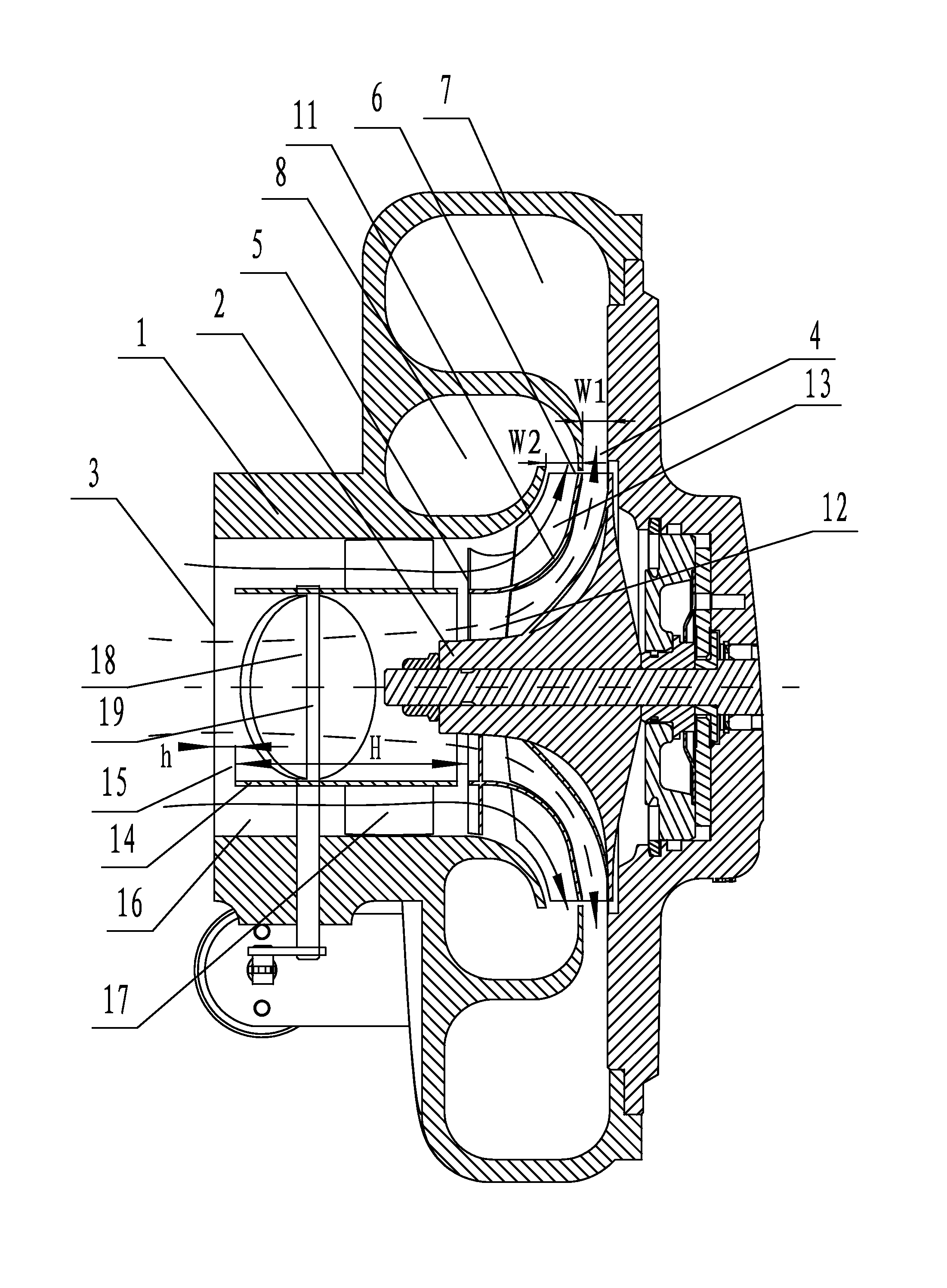
[0051]As shown in FIGS. 1-2, a compressor of a turbocharger comprises a compressor housing 1 and a compressor impeller 2 disposed inside the compressor housing 1. A compressor flow passage is disposed inside the compressor housing 1. The compressor housing 1 comprises: a compressor flow passage, a compressor air inlet 3, and a compressor air outlet. The compressor flow passage is connected to the compressor air inlet 3 and the compressor air outlet. The compressor impeller 2 comprises an impeller feeding flow passage. The impeller air feeding flow passage is connected to the compressor air inlet 3 and the compressor flow passage.

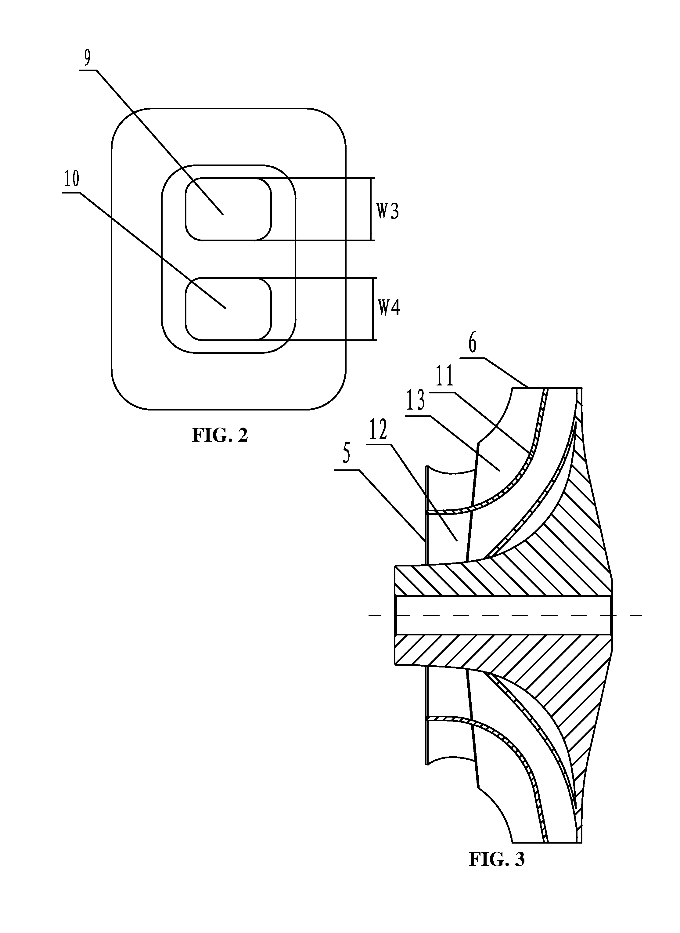
[0052]The compressor flow passage comprises a compressor inner flow passage 7 and a compressor outer flow passage 8 which are arranged side by side on the compressor housing. A ratio of a width W1 of an air inlet of the compressor inner flow passage 7 to a width W2 of an air inlet of the compressor outer flow passage 8 is between 0.1 and 10.

[0053]A compresso...

example 2

[0068]As shown in FIGS. 6-7, on the basis of Example 1, the butterfly valve 18 disposed inside the inner channel 15 of the compressor gas inlet is deleted. An adjustable valve 20 is disposed inside the compressor inner flow passage 7 in the vicinity of the air outlet 9 of the compressor inner flow passage. One end of the adjustable valve 20 is connected to a valve shaft 19. The valve shaft 19 is in transmission connection with a control mechanism. The adjustable valve 20 is driven by the control mechanism to rotate along the valve shaft 19 whereby opening or closing the compressor inner flow passage 7.

[0069]Working process of this example is as follows: as shown in FIG. 7, when the motor works at low speeds, the adjustable valve 20 is at the closed state (the adjustable valve is indicated as a solid line in the figure) under the drive of the control mechanism. Driven by the centrifugal force produced by the rotation of the compressor impeller 2, the fresh air is sucked into the oute...

example 3

[0070]As shown in FIGS. 8-9, on the basis of Example 2, the adjustable valve 20 disposed at the gas outlet 9 of the compressor inner flow passage is deleted. A plurality of adjustable guide vanes 21 is uniformly disposed in a circle inside the compressor diffuser 4 in the vicinity of the impeller air outlet 6. A ratio of a number of the fixed guide vanes 17 to a number of the adjustable guide vanes 21 is between 0.2 and 6.

[0071]As shown in FIG. 10, each adjustable guide vane 21 is in rotary connection with a fork lever 22. The fork level 22 is in rotary connection with a fork plate 23. The fork plate 23 is driven by a control mechanism to rotate so as to achieve rotation of the adjustable guide vanes 21 and to open or close the compressor inner flow passage 7.

[0072]The control mechanism in Example 3 is not limited to the fork lever control mechanism and can be control mechanisms of any structures.

[0073]Working process of this example is as follows: as shown in FIG. 11, when the moto...


PUM


Abstract

A compressor of a turbocharger including a compressor housing and a compressor impeller. The compressor housing includes: a compressor flow passage, a compressor air inlet, and a compressor air outlet. The compressor impeller includes an impeller feeding flow passage. The compressor impeller is disposed inside the compressor housing. The compressor flow passage is disposed inside the compressor housing. The compressor flow passage is connected to the compressor air inlet and the compressor air outlet. The impeller air feeding flow passage is connected to the compressor air inlet and the compressor flow passage.

Description

CROSS-REFERENCE TO RELATED APPLICATIONS[0001]This application is a continuation-in-part of International Patent Application No. PCT / CN2012 / 000713 with an international filing date of May 22, 2012, designating the United States, now pending, and further claims priority benefits to Chinese Patent Application No. 201210137085.9 filed May 7, 2012. The contents of all of the aforementioned applications, including any intervening amendments thereto, are incorporated herein by reference. Inquiries from the public to applicants or assignees concerning this document or the related applications should be directed to: Matthias Scholl P.C., Attn.: Dr. Matthias Scholl Esq., 245 First Street, 18th Floor, Cambridge, Mass. 02142.BACKGROUND OF THE INVENTION[0002]1. Field of the Invention[0003]The invention relates to a compressor of a turbocharger.[0004]2. Description of the Related Art[0005]A typical compressor of a turbocharger includes a single impeller and one flow passage. The compressor tends ...

Claims


Application Information

Patent Timeline
IPC IPC(8): F04D27/02F04D29/46F04D29/30F04D17/10
CPCF04D27/0253F04D17/10F04D29/30F04D29/462F04D27/0246F04D27/0269F04D29/4206F01D9/026F04D29/4213F05D2220/40F05D2240/40F05D2260/60F05D2270/101F04D29/286F05D2250/52F05D2250/51
Inventor WANG, HANGLI, YONGTAIZHU, ZHIFULI, YANZHAOYUAN, DAOJUNWANG, YANXIASONG, LIHUA
Owner WANG HANG
Why Eureka
Try Eureka