
System for inductive heating of turbine rotor disks

a technology of inductive heating and turbine rotor disk, which is applied in the direction of engine ignition, electric/magnetic/electromagnetic heating, turbine/propulsion engine, etc., can solve the problem of inductive heating of the part of the rotor disk, and achieve the effect of faster heating, increased operational flexibility of the turbine, and faster start speed of the turbine rotor

Inactive Publication Date: 2015-03-12
SIEMENS AG
View PDF31 Cites 3 Cited by
  • Summary
  • Abstract
  • Description
  • Claims
  • Application Information

AI Technical Summary

Benefits of technology

The invention is about a system and method for heating different parts of a gas turbine, particularly the rotor disk. The goal is to provide a simple, efficient, and cost-effective solution for achieving this heating.

Problems solved by technology

The Eddy currents so generated in the part of the rotor disk result in inductive heating of the part of the rotor disk.

Method used


Image

  • System for inductive heating of turbine rotor disks
  • System for inductive heating of turbine rotor disks
  • System for inductive heating of turbine rotor disks

Examples


Embodiment Construction

[0039]Hereinafter, the best mode for carrying out the present invention is described in details. Various embodiments are described with reference to the drawings, wherein like reference numerals are used to refer to like elements throughout.

[0040]In the following description, for purpose of explanation, numerous specific details are set forth in order to provide a thorough understanding of one or more embodiments. It may be evident that such embodiments may be practiced without these specific details.

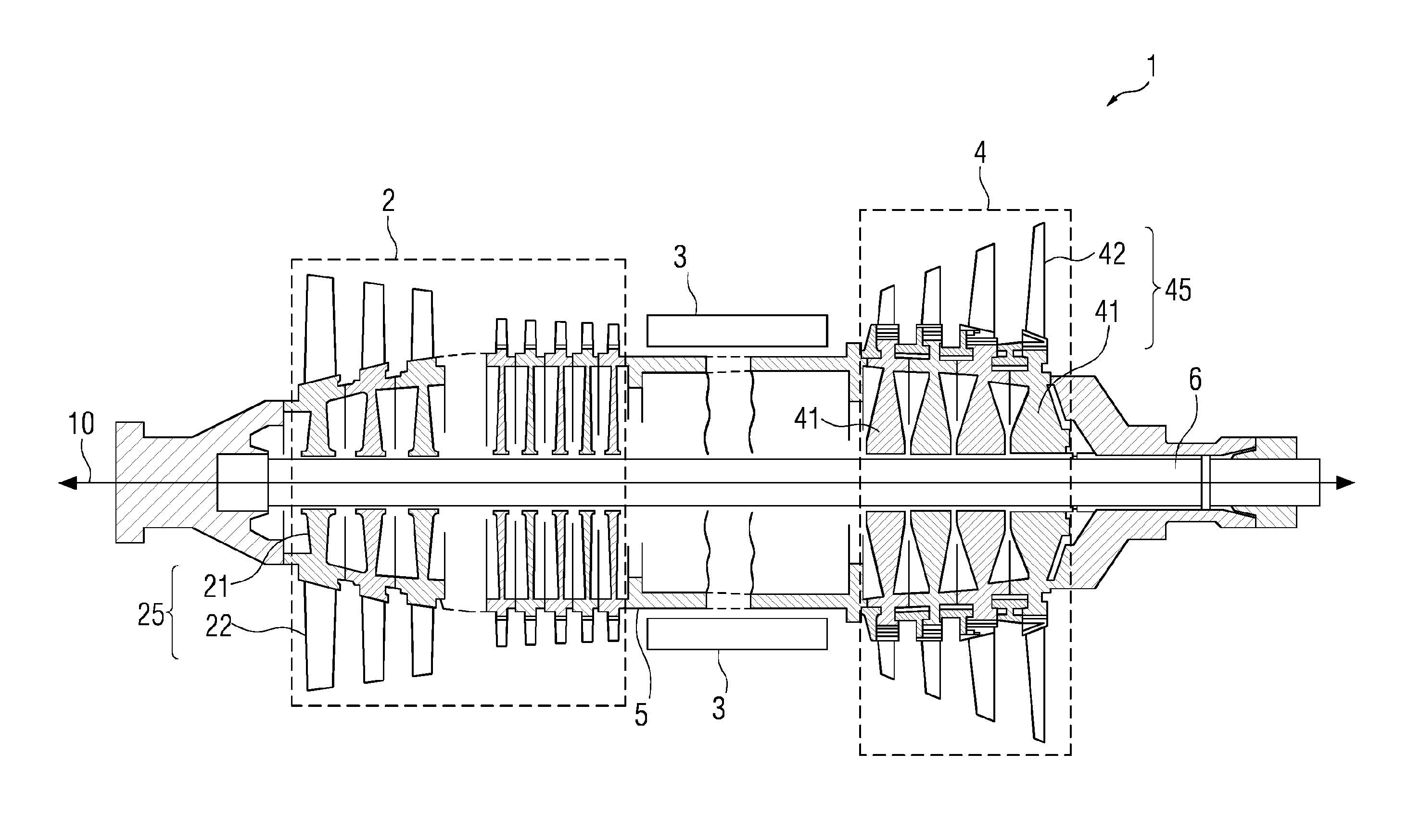
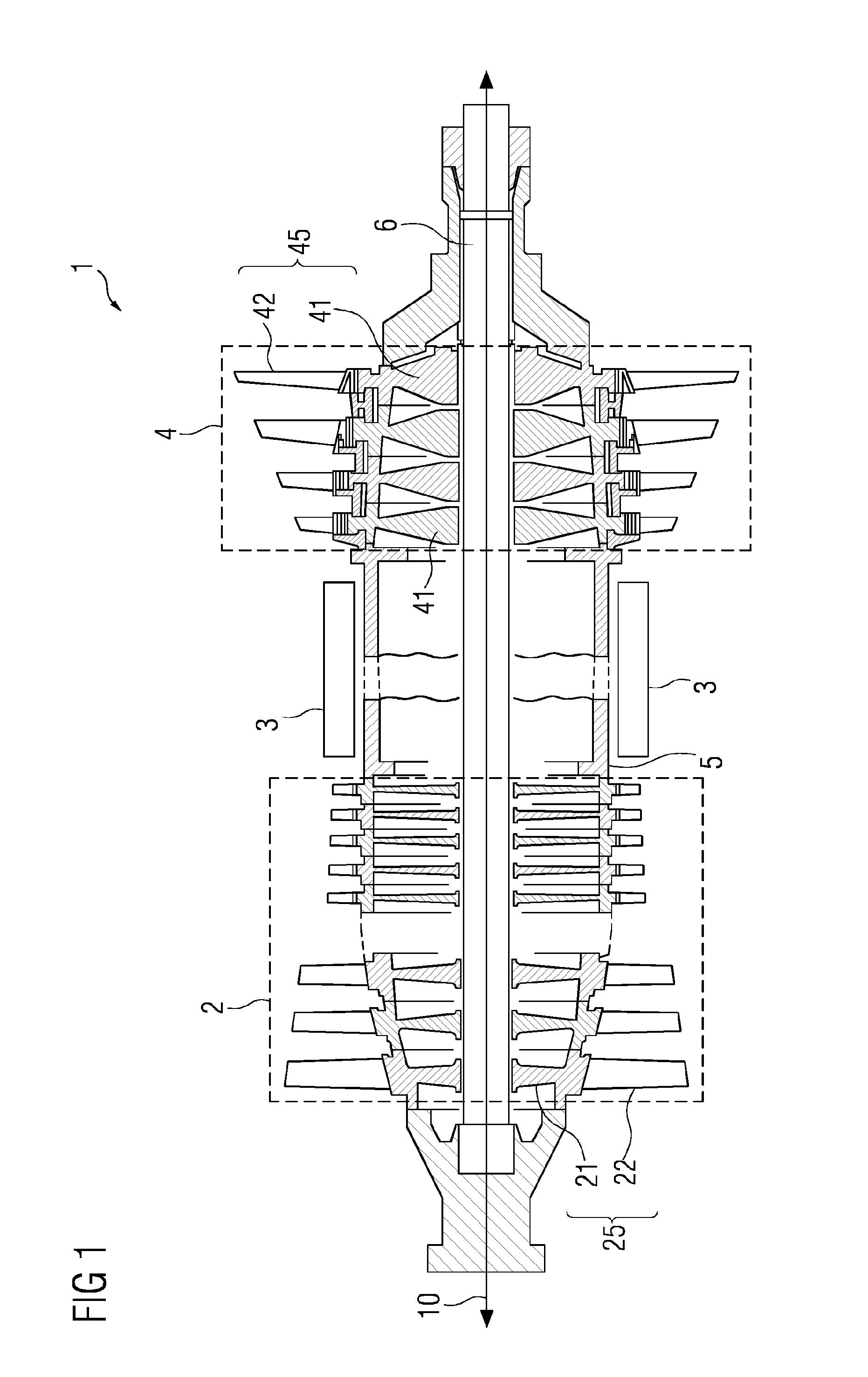
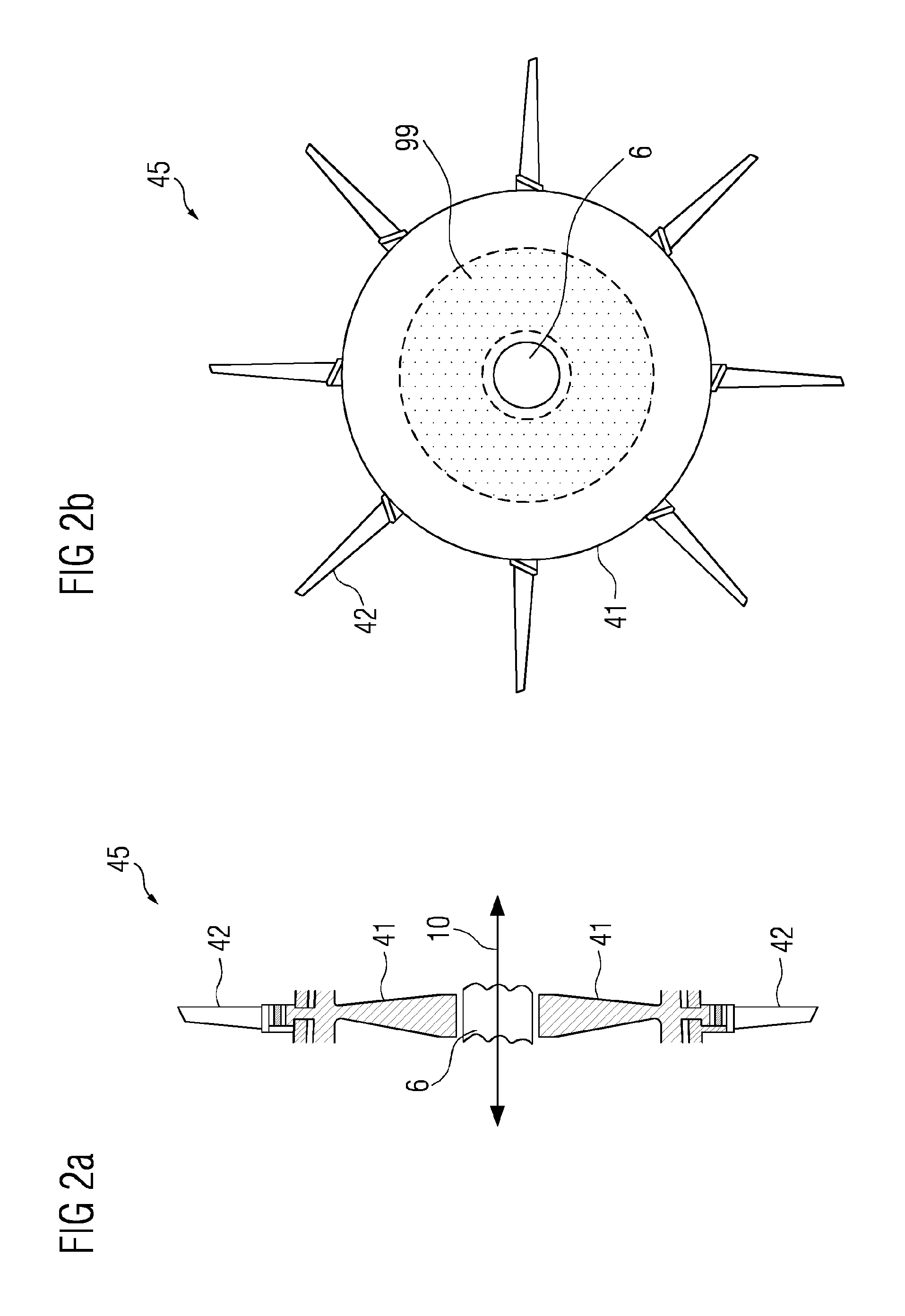
[0041]Referring to the figures, FIG. 1 schematically represents a typical gas turbine 1 and shows a cross-sectional side view of the same. The gas turbine 1 typically contains an inlet (not shown) for atmospheric air, a compressor unit 2 having rotatable compressor rotors 25, a combustion unit 3, a turbine unit 4 having rotatable turbine rotors 45 and an outlet (not shown).

[0042]Atmospheric air is received by the inlet and passed to the compressor unit 2 where the air undergoes compress...


PUM


Abstract

A turbine rotor with at least one rotor disk is provided. The turbine rotor includes a heating arrangement for heating at least a part of the rotor disk. The heating arrangement has a conductor for conducting electric current. The conductor is positioned such that in presence of the electric current in the conductor, Eddy current is generated in the part of the rotor disk. The electric current is an alternating current. The Eddy currents so generated in the part of the rotor disk result in inductive heating of the part of the rotor disk.

Description

CROSS REFERENCE TO RELATED APPLICATIONS[0001]This application is the US National Stage of International Application No. PCTEP2013055331 filed Mar. 15, 2013, and claims the benefit thereof. The International Application claims the benefit of European Application No. EP12161503 filed Mar. 27, 2012. All of the applications are incorporated by reference herein in their entirety.FIELD OF INVENTION[0002]The invention relates to a system and a method for heating of parts of a gas turbine, and more particularly to a system and a method for heating of rotor disks of a gas turbine.BACKGROUND OF INVENTION[0003]Some parts in a gas turbine with high operating temperatures are constantly subjected to cyclic mechanical stresses. One example of such part, as is well known, is the turbine rotor containing rotor disks and blades, the blades radially extending outwards from the rotor disks of the turbine rotors. The disks rotate due to the movement of the hot gases through the blades of the turbine ro...

Claims


Application Information

Patent Timeline
Patent Type & Authority Applications(United States)
IPC IPC(8): F01D25/10F02C7/26
CPCF02C7/26F01D25/10F01D5/08F01D19/02F05D2260/85F01D5/02F01D5/06H05B6/102
Inventor EXNOWSKI, SVENKULIG, STEFANNIMPTSCH, HARALD
Owner SIEMENS AG
Learn More