Fuel delivery system including integrated check valve

a fuel delivery system and check valve technology, applied in liquid fuel feeders, machines/engines, pumping plants, etc., can solve the problems of reducing combustion efficiency, reducing the longevity of the pump, reducing the fuel consumption, etc., and increasing the combustion efficiency. , the effect of reducing the consumption of fuel

Active Publication Date: 2015-03-12
FORD GLOBAL TECH LLC
View PDF34 Cites 12 Cited by
  • Summary
  • Abstract
  • Description
  • Claims
  • Application Information

AI Technical Summary

Benefits of technology

[0002]Fuel delivery systems are used in vehicles to provide fuel to cylinders in the engine. Some fuel delivery systems may include multiple fuel pumps, such as a high pressure fuel pump and a low pressure fuel pump, to providing high pressure fuel to the cylinders. Increasing the pressure of the fuel delivery system may enable combustion efficiency to be increased, thereby reducing fuel consumption and / or increasing power output. However, fuel delivery systems may experience pressure pulsations in a variety of locations in the system. For instance, pressure pulses may be experienced between the fuel pumps and between the fuel rail and the high pressure fuel pump. As a result, the longevity of the pumps, fuel rail, etc., may be decreased due to the degradation of components caused by the pressure pulsations in the system. These pressure pulsations may also negatively affect the metering of the fuel provided to the combustion chamber, thereby reducing combustion efficiency. Moreover, the noise, vibration, and harshness (NVH) caused by the pulsations also decreases customer satisfaction.

Problems solved by technology

However, fuel delivery systems may experience pressure pulsations in a variety of locations in the system.
As a result, the longevity of the pumps, fuel rail, etc., may be decreased due to the degradation of components caused by the pressure pulsations in the system.
These pressure pulsations may also negatively affect the metering of the fuel provided to the combustion chamber, thereby reducing combustion efficiency.
Moreover, the noise, vibration, and harshness (NVH) caused by the pulsations also decreases customer satisfaction.
As a result, the bulkiness of the fuel delivery system is increased.
This type of shape increases losses in the fuel delivery system.

Method used


Image

  • Fuel delivery system including integrated check valve
  • Fuel delivery system including integrated check valve
  • Fuel delivery system including integrated check valve

Examples


Embodiment Construction

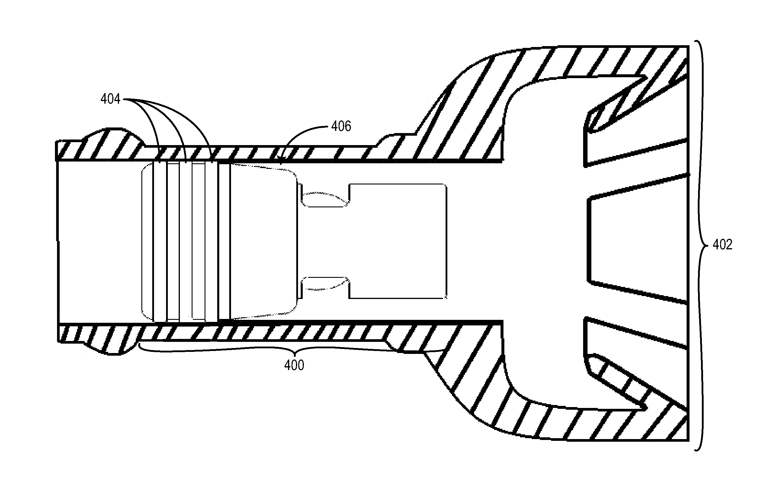
[0013]A fuel delivery system is described herein. The fuel delivery system includes check valve positioned in an elastic fuel line. The check valve includes an external housing having a peripheral surface with a greater diameter than an unstretched inner diameter of the elastic fuel line. Sizing the check valve and fuel line in this manner enables the check valve to be securely integrated into the fuel line, without splitting the fuel line to add a standalone check valve assembly, if desired. As a result, the compactness of the fuel delivery system may be increased through the integration of the check valve into an existing fuel line, if desired. Additionally, it will be appreciated that the pressure pulsations may be generated by operation of a fuel pump upstream of the check valve. It will be further appreciated, that the check valve is configured to enable fuel to flow therethrough in a downstream direction when the pressure in the fuel line exceeds a threshold value. As a result...


PUM


Abstract

A fuel delivery system is provided to reduce the pressure pulsations and noise vibration and harshness of direct injection systems. The fuel delivery system includes an elastic fuel line positioned between a first fuel pump and a second fuel pump and a check valve positioned in the elastic fuel line near the inlet of the high pressure pump, the check valve including an external housing having a peripheral surface with a greater diameter than an unstretched inner diameter of the elastic fuel line.

Description

FIELD[0001]The present disclosure relates to a fuel delivery system in an engine.BACKGROUND AND SUMMARY[0002]Fuel delivery systems are used in vehicles to provide fuel to cylinders in the engine. Some fuel delivery systems may include multiple fuel pumps, such as a high pressure fuel pump and a low pressure fuel pump, to providing high pressure fuel to the cylinders. Increasing the pressure of the fuel delivery system may enable combustion efficiency to be increased, thereby reducing fuel consumption and / or increasing power output. However, fuel delivery systems may experience pressure pulsations in a variety of locations in the system. For instance, pressure pulses may be experienced between the fuel pumps and between the fuel rail and the high pressure fuel pump. As a result, the longevity of the pumps, fuel rail, etc., may be decreased due to the degradation of components caused by the pressure pulsations in the system. These pressure pulsations may also negatively affect the met...

Claims


Application Information

Patent Timeline
Patent Type & Authority Applications(United States)
IPC IPC(8): F02M37/00F16K47/08
CPCF16K47/08F02M37/0041
Inventor JENSEN, JACOBYU, DEQUANMORGAN, DENNISWOODRING, CHRISTOPHER ARNOLD
Owner FORD GLOBAL TECH LLC
Why Eureka
Try Eureka