
Eureka
For R&D, Eureka makes reading and utilizing patents & technical documents easy.
Eureka AIR
Designed for self-driven R&D workflows. Generate viable solutions, solve complex R&D challenges, empower your innovation with AI.

Eureka Materials
Designed for material experts only. Revolutionize your material R&D, from search, analyze, to developing new materials.

TechResearch
Generate reliable direction feasibility study reports for your R&D in just a few steps.

TechSeek
Discover and master advanced knowledge NOW. Basics, ideas, possibilities, all at once.

TechMind
As an expert in R&D Theories, TechMind can generates customized viable solutions instantly.

TechRisk
Analyze your overall solution with one click, know your potential R&D risks in advance.

TechMonitor
Get weekly tech updates, stay abreast of the latest tech innovations and key insights.
Wireless communication system, wireless communication device, and wireless communication method
- Summary
- Abstract
- Description
- Claims
- Application Information
AI Technical Summary
Benefits of technology
Problems solved by technology
Method used
Image

Examples
first embodiment
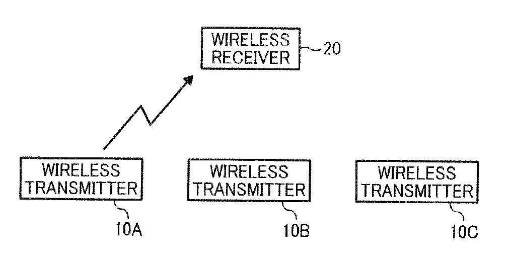
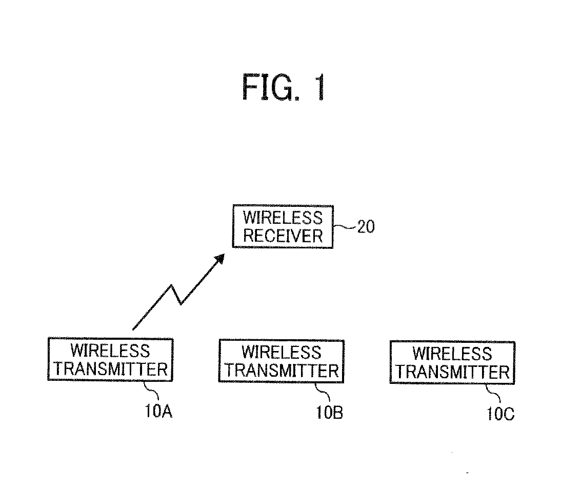
[0027]FIG. 1 is a schematic diagram illustrating a wireless communication system in the first embodiment. The wireless communication system in FIG. 1 includes multiple wireless transmitters 10A, 10B, and 10C and a wireless receiver 20 and transfers the TS packets of MPEG-2 wirelessly. Examples of the wireless transmitters 10A, 10B, and IOC are a tuner and a DVD player etc. The wireless transmitters 10A, 10B, and 10C acquires input data that includes the video signal and audio signal (ES data), encodes it to the TS packet, and transfers a wireless frame that includes the TS packet to the wireless receiver 20 wirelessly. The wireless receiver 20 includes a display and a speaker for example. The wireless receiver 20 decodes the TS packet included in the wireless frame received from any one of the wireless transmitters 10A, 10B, and IOC wirelessly, acquires the original video signal and audio signal, synchronizes them, and outputs them from the display and the speaker.
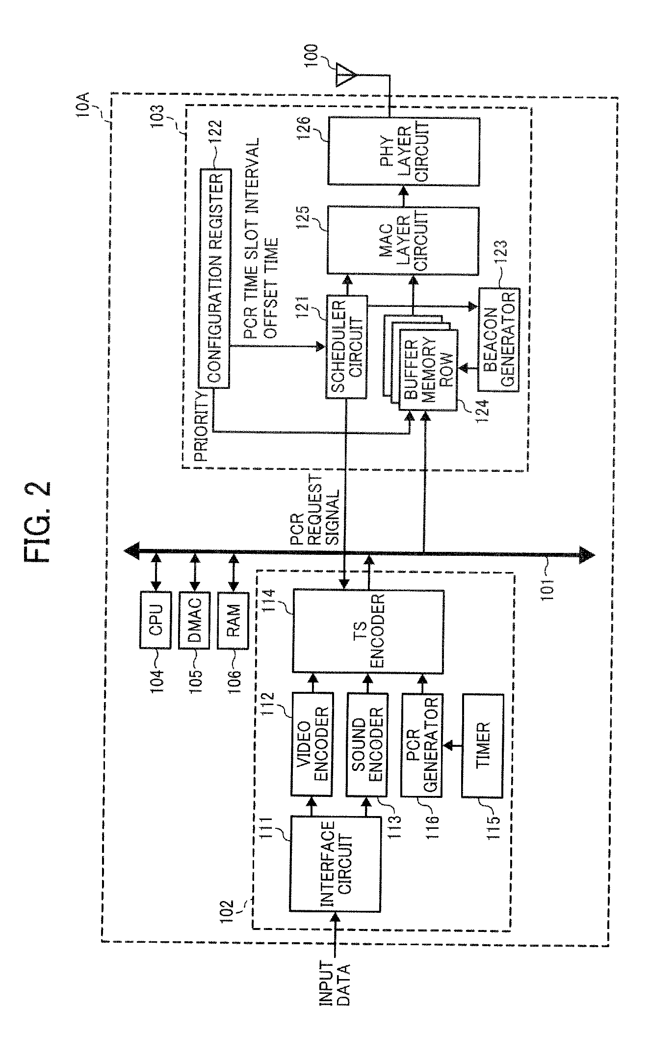
[0028]FIG. 2 is a ...
second embodiment
[0047]In the first embodiment described above, the wireless transmitter 10A and the wireless receiver 20 specify the OCR time slot in accordance with the predetermined rule. However, the wireless transmitter 10A and the wireless receiver 20 can share the information on specifying the PCR time slot in other ways. In this embodiment, the wireless transmitter 10A reports the information on specifying the PCR time slot to the wireless receiver 20 using the beacon frame.
[0048]FIG. 8 is a diagram illustrating format of an ASIE field included in the beacon frame transferred in the wireless communication system in this embodiment. Vendor's original format can be configured to the ASIE field in the beacon frame. In FIG. 8, the ASIE field includes a PCR transmission MAS field and PCR transmission flag field as application specification information. The PCR transmission MAS field indicates the number of the PCR time slot in case of transferring the wireless frame that includes the TS packet wi...
PUM
 Abstract
Description
Claims
Application Information
 - R&D Engineer
- R&D Manager
- IP Professional
- Industry Leading Data Capabilities
- Powerful AI technology
- Patent DNA Extraction
Browse by: Latest US Patents, China's latest patents, Technical Efficacy Thesaurus, Application Domain, Technology Topic, Popular Technical Reports.
© 2024 PatSnap. All rights reserved.Legal|Privacy policy|Modern Slavery Act Transparency Statement|Sitemap|About US| Contact US: help@patsnap.com