Radio measurement method and radio measurement apparatus using multi-antenna channel multiplex

a radio measurement and multi-antenna channel technology, applied in the direction of direction finders using radio waves, multiplex communication, digital transmission, etc., can solve the problems of inconvenient measurement of the overall radio measurement, inconvenient configuration of the radio receiving apparatus, and inability to achieve the effect of reducing noise, reducing radiation wave shadow influence, and improving accuracy

Active Publication Date: 2015-03-12
ELECTRONICS & TELECOMM RES INST
View PDF6 Cites 19 Cited by
  • Summary
  • Abstract
  • Description
  • Claims
  • Application Information

AI Technical Summary

Benefits of technology

[0020]In accordance with the present invention, a reference antenna is selected from two antenna arrays that can avoid radio wave shadow in a possible signal arrival direction with respect to a received channel, and radio waves are measured through a channel multiplex with respect to other antenna arrays in the radio measurement apparatus for signal spectrum measurement and signal direction estimation. Accordingly, radio wave shadow influence can be reduced, noise can be reduced using dual channel phase-spectrum analysis and dual channel cross spectrum and the signal arrival direction of a multi-channel signal can be measured more accurately.

Problems solved by technology

The array antenna configuration has the problem that it may accompany performance deterioration due to the radio shield phenomenon of an antenna mast for supporting the array antenna or antenna elements.
However, it is inefficient in space and cost to configure a radio receiving apparatus that is composed of a plurality of receiving channels corresponding to antenna channels in the radio measurement system.
Further, if the received signal characteristics of the reference receiving channel are not satisfactory due to the radio wave shadow of the antenna or the mast, the overall radio measurement is affected thereby.

Method used


Image

  • Radio measurement method and radio measurement apparatus using multi-antenna channel multiplex
  • Radio measurement method and radio measurement apparatus using multi-antenna channel multiplex
  • Radio measurement method and radio measurement apparatus using multi-antenna channel multiplex

Examples


Embodiment Construction

[0028]Hereinafter, the operation principle of the present invention will be described in detail with reference to the accompanying drawings. In explaining the present invention, a detailed description of known functions and configurations incorporated herein will be omitted when it may make the subject matter of the present invention rather unclear. Also, the following terms are defined considering functions of the present invention, and may be differently defined according to the intention of an operator or custom. Therefore, the terms should be defined based on the overall contents of the specification.

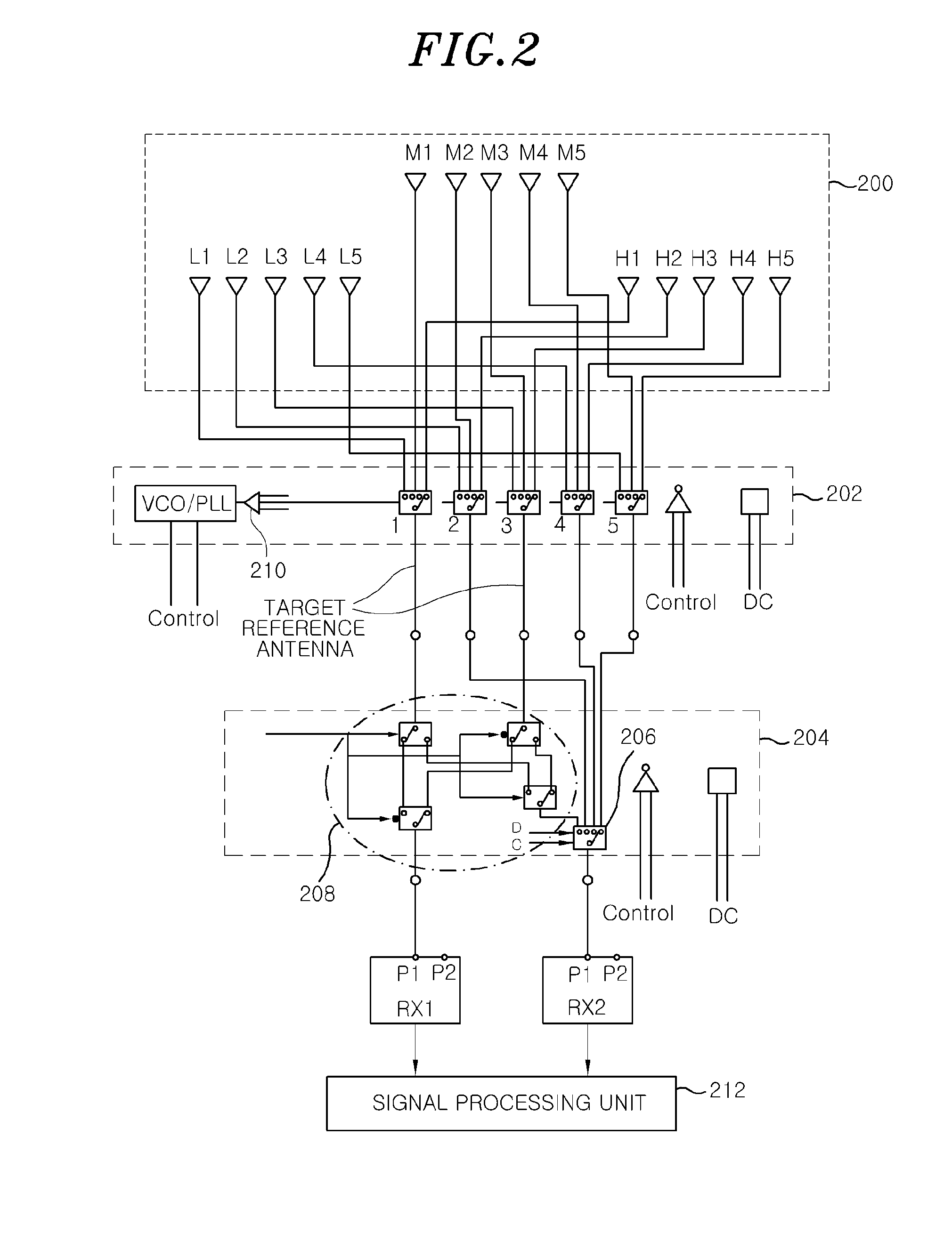
[0029]FIG. 2 is a diagram illustrating the configuration of a dual-channel radio measurement system using a reference channel variation technology according to an embodiment of the present invention,

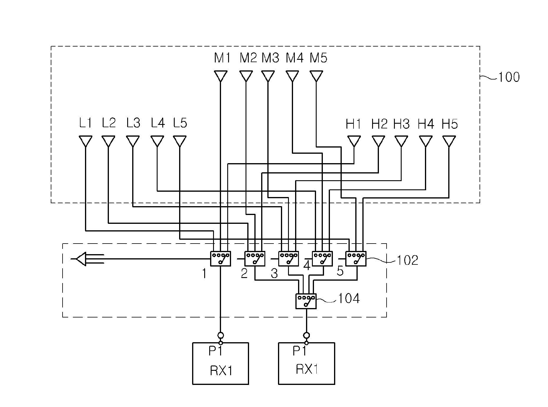
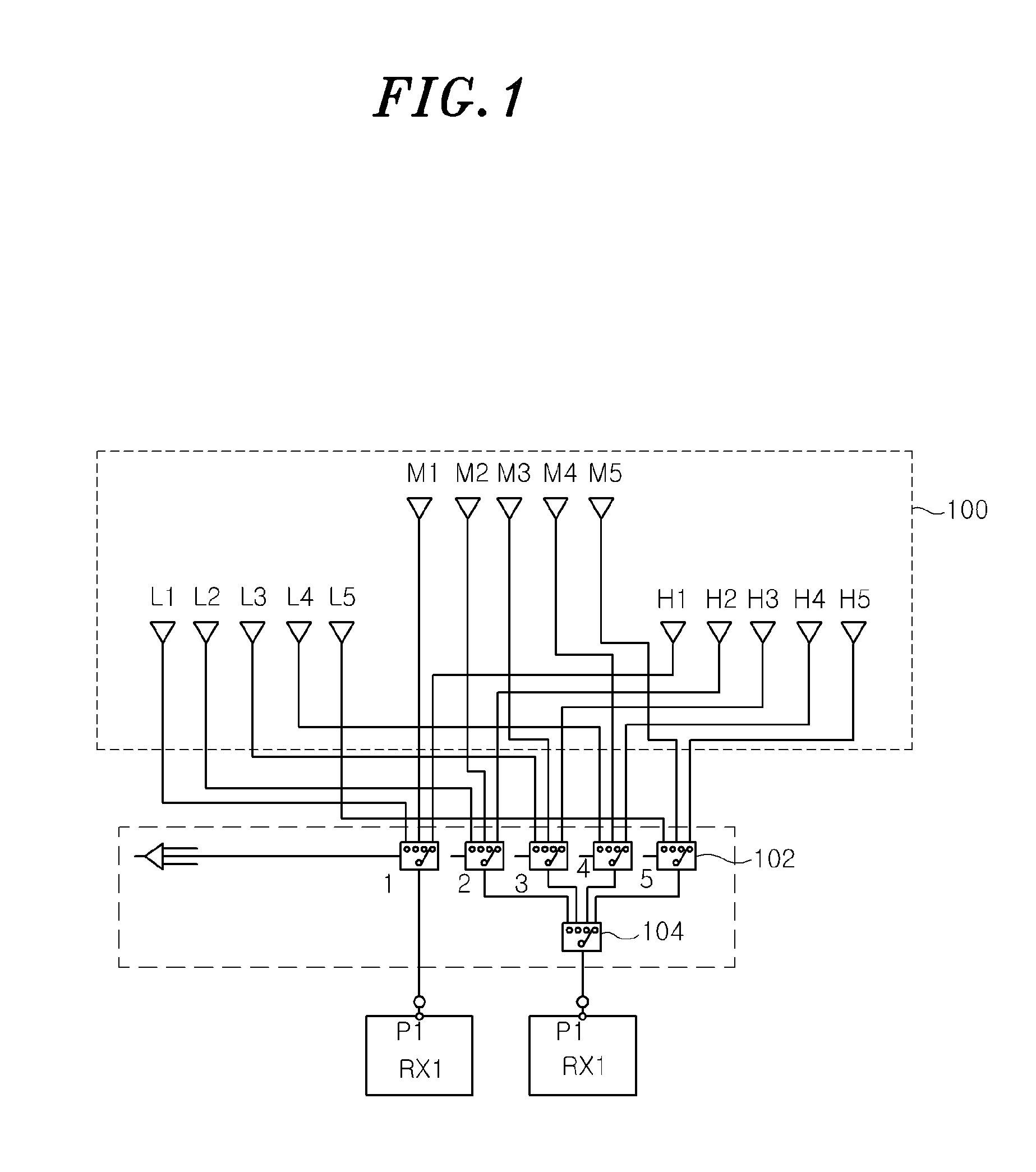
[0030]Referring to FIG. 2, a multi-channel array antenna unit includes a plurality of multi-channel antennas for receiving different frequency band signals. In the present invention, it ...


PUM


Abstract

A radio measurement apparatus comprising: an array antennal selection unit selecting array antennas corresponding to received signals; a reference path selection unit selecting a reference array antenna; a signal processing unit selecting a reference antenna channel through analysis of signal characteristics measured through two reception channels; a sequential channel multiplex unit determining sequentially inputting received signals of remaining array antennas to output the sequentially input signals to a receiver; and a correction signal input unit compensating amplitude and phase characteristics of the respective reception channels.

Description

RELATED APPLICATIONS[0001]This application claims the benefit of Korean Patent Application No. 10-2013-0108586, filed on Sep. 10, 2013, which is hereby incorporated by reference as if fully set forth herein.FIELD OF THE INVENTION[0002]The present invention relates generally to radio measurement, and more particularly to a radio measurement method and a radio measurement apparatus using multi-antenna channel multiplex, which can reduce radio wave shadow influence, reduce noise using dual channel phase-spectrum analysis and dual channel cross spectrum, and measure signal arrival direction of a multi-channel signal more accurately by variably selecting a reference antenna from an antenna array that can avoid radio wave shadow in a possible signal arrival direction with respect to a received channel and measuring radio waves through a channel multiplex with respect to other antenna arrays in the radio measurement apparatus for signal spectrum measurement and signal direction estimation....

Claims


Application Information

Patent Timeline
Patent Type & Authority Applications(United States)
IPC IPC(8): H04L7/00
CPCH04L7/0016H04B7/086H04B7/0874G01S3/04G01S3/12G01S3/14
Inventor KIM, SANG TAEPARK, GWANGMOONLEE, SEONG YUNRO, HAENG SOOKSUK, MI-KYUNGCHOI, YONG-SEOK
Owner ELECTRONICS & TELECOMM RES INST
Why Eureka
Try Eureka