Cutting insert with finishing and roughing cutting edges

a cutting edge and insert technology, applied in the direction of cutting inserts, shaping cutters, manufacturing tools, etc., can solve the problems of time-consuming and expensive operations

Active Publication Date: 2015-03-12
KENNAMETAL INC
View PDF15 Cites 13 Cited by
  • Summary
  • Abstract
  • Description
  • Claims
  • Application Information

AI Technical Summary

Benefits of technology

[0005]The problem of providing a fine surface finish, particularly on a workpiece made of metal, is solved by designing a cutting insert with both primary wiper cutting edges and secondary roughing cutting edges that are presented to the workpiece when the cutting insert is isometrically mounted in a pocket of a cutter body. In addition, by designing a cutting insert with both primary wiper cutting edges and secondary roughing cutting edges that are presented to the workpiece when the cutting insert is tangentially mounted in the pocket of the cutter body.

Problems solved by technology

Such operations are time consuming and expensive since multiple cutting inserts must be used to machine a single workpiece to a desired shape and operations must be periodically halted in order to replace the inserts for different cutting operations.

Method used


Image

  • Cutting insert with finishing and roughing cutting edges
  • Cutting insert with finishing and roughing cutting edges
  • Cutting insert with finishing and roughing cutting edges

Examples


Embodiment Construction

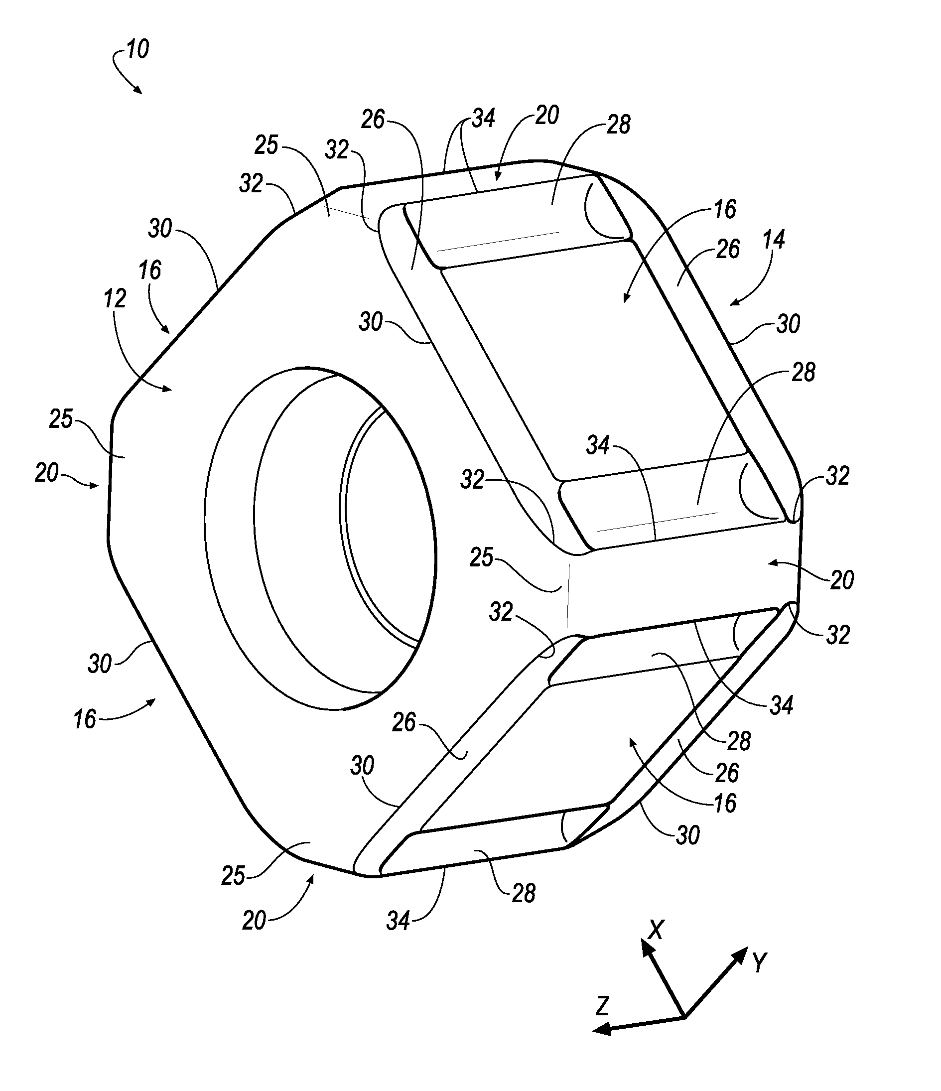
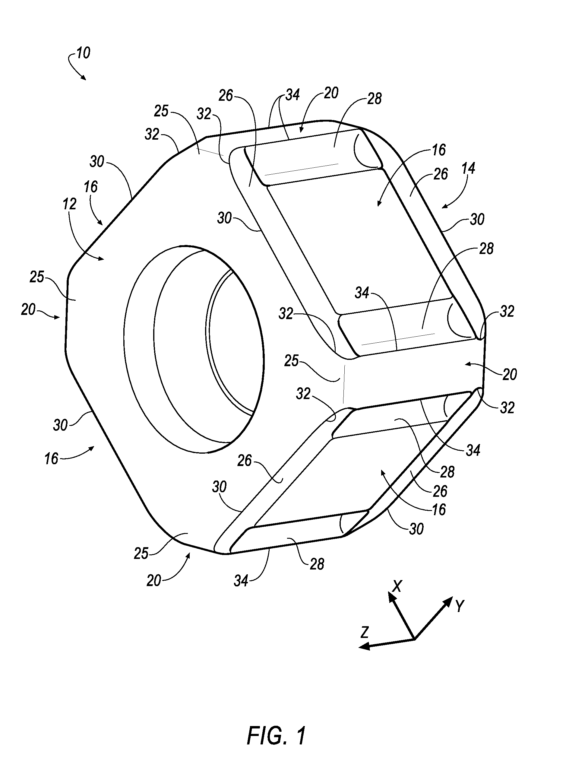
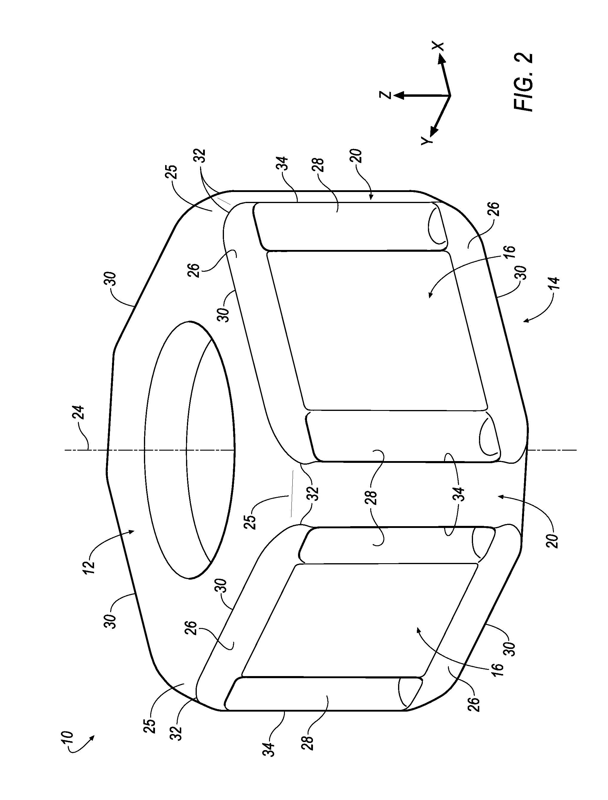
[0020]Referring now to FIGS. 1-6, an indexable cutting insert 10 is shown according to an embodiment of the invention. In general, the cutting insert 10 has a polygonal body made of a wear-resistant material of a type known in the art. The cutting insert 10 is of a generally cubic in shape that includes a top surface 12, a bottom surface 14 that is parallel and identical to the top surface 12, and a plurality of side surfaces 16 that are identical to each other. As shown in FIG. 3, the cutting insert 10 has four (4) side surfaces 16, each side surface 16 has an angle 18 of approximately ninety (90) degrees with respect to an adjacent side surface 16.

[0021]In the illustrated embodiment, each side surface 16 is substantially perpendicular to both the top and bottom surfaces 12, 14. In other words, the top and bottom surfaces 12, 14 are substantially parallel to each other and perpendicular to the side surfaces 16. That is, the side surfaces 16 have a clearance angle of zero (0) degree...


PUM

PropertyMeasurementUnit
angleaaaaaaaaaa
angleaaaaaaaaaa
angleaaaaaaaaaa

Abstract

An indexable cutting insert includes a top surface, a bottom surface and a plurality of side surfaces. Each side surface includes a first pair of chip grooves, and a second pair of chip grooves. A planar corner surface is disposed between each side surface. A corner radius extends between the top and bottom surfaces and the planar corner surface. A plurality of primary wiper cutting edges are formed at an intersection between each of the first pair of chip grooves and the the top and bottom surfaces. A plurality of secondary roughing cutting edges are formed at an intersection between each corner radius and each of the first pair of chip forming grooves. A plurality of wiper cutting edges are formed at an intersection between each planar corner surface and each of the second pair of chip forming grooves. A milling cutter is also disclosed.

Description

BACKGROUND OF THE INVENTION[0001]1. Field of the Invention[0002]The invention pertains to the field of indexable cutting inserts. More particularly, the invention pertains to an indexable cutting insert having a plurality of primary finishing cutting edges and a plurality of secondary roughing cutting edges.[0003]2. Description of Related Art[0004]Typical metalworking operations are conducted with a machine tool or similar equipment using a cutting insert. First, machining is undertaken with one or more inserts suitable for rough cutting, which removes large amounts of material from a workpiece but leaves a relatively rough surface finish. Then, the roughly turned surface is machined by another insert configured to give the workpiece a finished cut. Such operations are time consuming and expensive since multiple cutting inserts must be used to machine a single workpiece to a desired shape and operations must be periodically halted in order to replace the inserts for different cuttin...

Claims


Application Information

Patent Timeline
Patent Type & Authority Applications(United States)
IPC IPC(8): B23C5/20
CPCB23C5/207B23C2200/208B23C2200/0461B23C5/06B23C5/202B23B2222/14B23B2200/087B23C2200/367Y10T407/1942Y10T407/235B23C5/20B23C2210/486B23C5/205B23C2200/326
Inventor MORRISON, LEWIS RAYIYER, RAVISHANKAR
Owner KENNAMETAL INC
Why Eureka
Try Eureka