
Wavefront measuring apparatus, wavefront measuring method, method of manufacturing optical element, and assembly adjustment apparatus of optical system

a technology of wavefront and measuring method, applied in the direction of optical measurement, optical radiation measurement, instruments, etc., can solve the problems of increasing measurement inaccuracy, time and cost in preparing compensators, and difficulty or impossible in re-creating test wavefronts with shwfs, and achieve high-quality low-cost measurements.

Inactive Publication Date: 2015-03-12
CANON KK
View PDF10 Cites 13 Cited by
  • Summary
  • Abstract
  • Description
  • Claims
  • Application Information

AI Technical Summary

Benefits of technology

The present invention provides a device and method for accurately measuring the wavefront of an optical element that has a lot of distortion, as well as a way to make these optical elements and adjust the assembly of the optical system. This invention is affordable and effective, and can help improve the performance of optical systems.

Problems solved by technology

However, a large displacement of the test wavefront makes it difficult or impossible to reconstruct the test wavefront with the SHWFS.
79, correcting the displacement of the test wavefront with the compensator to be within the dynamic range of the wavefront measuring sensor adversely increases measurement inaccuracy due to an arrangement error and an shape error of the compensator.
In addition, the compensator needs to be highly accurately designed and manufactured, which takes time and cost in preparing the compensator.
Furthermore, since each test optical system as a measurement target requires a corresponding compensator, an increase in the type of the test optical system leads to an increase in the type of the compensator and thus an increase in wavefront measuring cost.

Method used


Image

  • Wavefront measuring apparatus, wavefront measuring method, method of  manufacturing optical element, and assembly adjustment apparatus of  optical system
  • Wavefront measuring apparatus, wavefront measuring method, method of  manufacturing optical element, and assembly adjustment apparatus of  optical system
  • Wavefront measuring apparatus, wavefront measuring method, method of  manufacturing optical element, and assembly adjustment apparatus of  optical system

Examples


embodiment 1

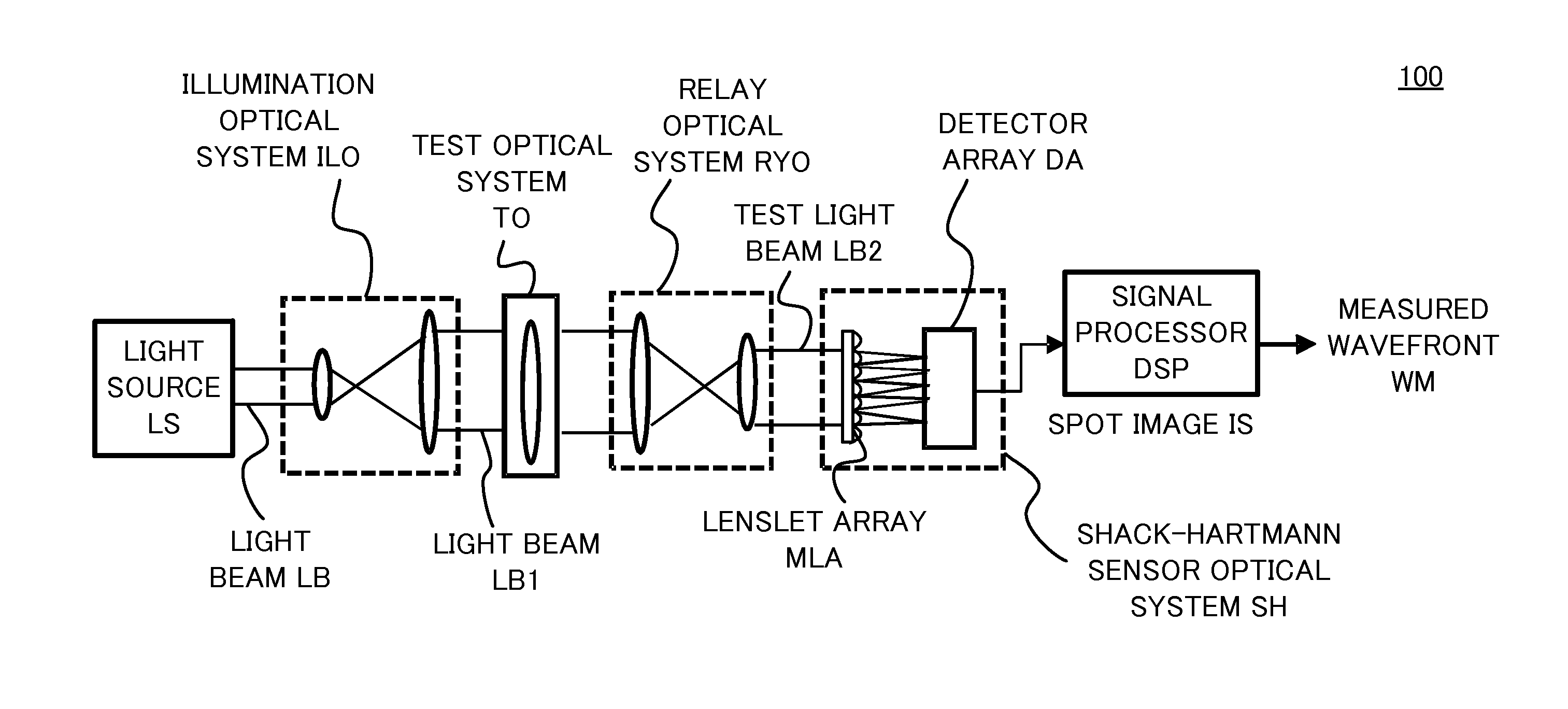
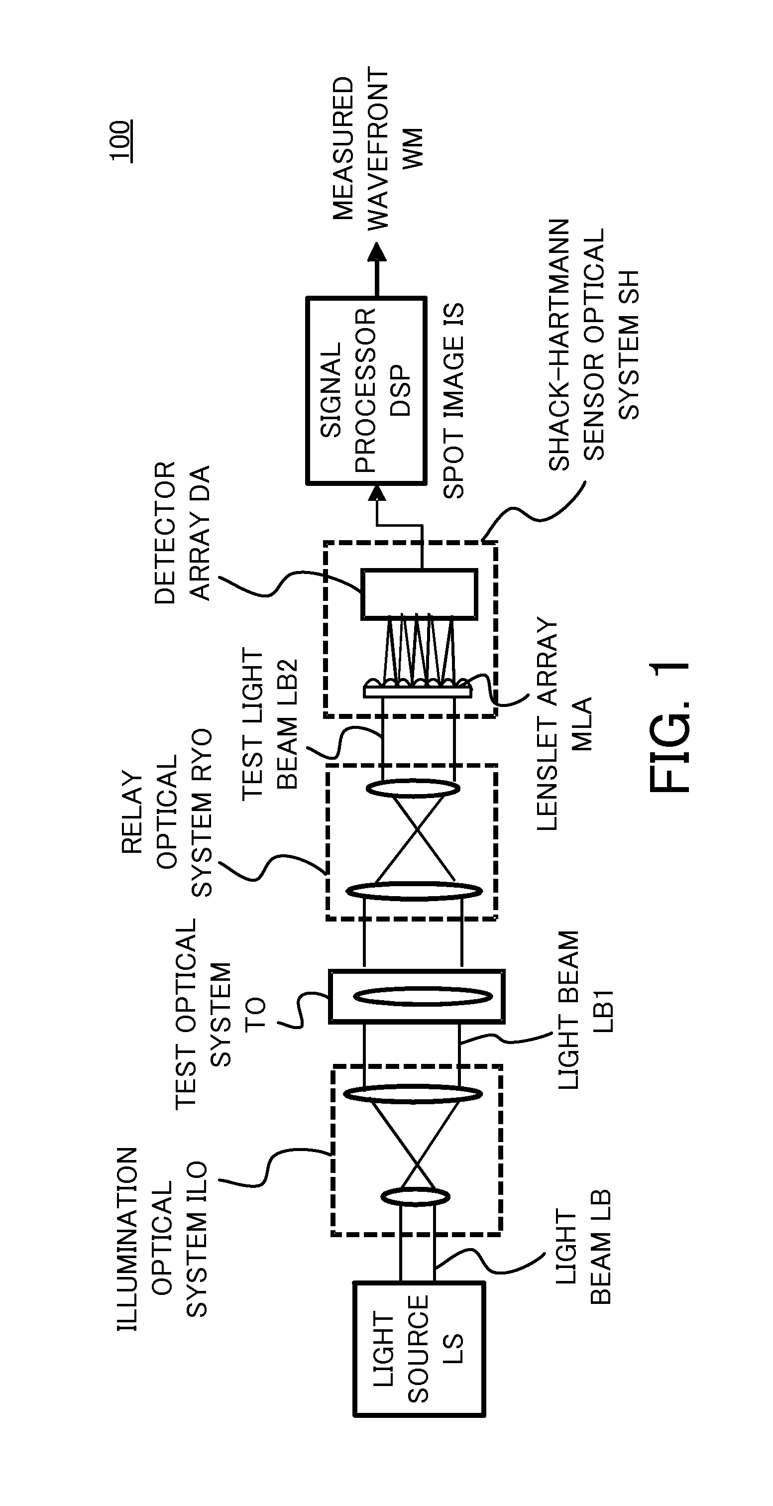
[0030]First, a wavefront measuring apparatus in Embodiment 1 of the present invention will be described. FIG. 1 is a main part configuration diagram of a wavefront measuring apparatus 100 in the present embodiment. The wavefront measuring apparatus 100 is configured to measure a transmitted wavefront or reflected wavefront of a test optical system (optical element).

[0031]In the wavefront measuring apparatus 100, a light beam LB from a light source LS is incident on an illumination optical system ILO. The illumination optical system ILO shapes the light beam LB into a desired light beam LB1. For example, the illumination optical system ILO is capable of extending a divergent light from an optical fiber or a pinhole into the light beam LB1 that covers a measurement region of the test optical system TO (an optical element to be measured). The illumination optical system ILO is also capable of adjusting the light quantity and the polarized state through an ND filter and a polarized filt...

embodiment 2

[0073]Next, a wavefront measuring apparatus in Embodiment 2 of the present invention will be described. The wavefront measuring apparatus 100 in Embodiment 1 includes the relay optical system RYO that images the test light beam LB2 (a wavefront on the pupil of the test optical system TO) onto the lenslet array MLA. In contrast, a wavefront measuring apparatus 100a in the present embodiment includes a simpler optical system in place of the relay optical system RYO so as to be capable of measuring a larger wavefront.

[0074]FIG. 12 is a main part configuration diagram of the wavefront measuring apparatus 100a in the present embodiment. The wavefront measuring apparatus 100a includes a convergent optical system CVO (scaling optical system) in place of the relay optical system RYO. The convergent optical system CVO scales the diameter of a light beam so that the test light beam LB2 is incident within the lenslet array MLA. The present embodiment uses the convergent optical system CVO havi...

embodiment 3

[0077]Next, a wavefront measuring apparatus in Embodiment 3 of the present invention will be described. The wavefront measuring apparatuses 100, 100a, and 100b in Embodiments 1 and 2 are designed to make the size of the test light beam LB2 equal to or smaller than the sizes of the lenslet array MLA and the detector array DA. In contrast, in the wavefront measuring apparatus in the present embodiment, the test light beam LB2 may be larger than the size of the lenslet array MLA due to divergent light.

[0078]FIG. 14 is a main part configuration diagram of a wavefront measuring apparatus 100c in the present embodiment. The wavefront measuring apparatus 100c causes the lenslet array MLA and the detector array DA (Shack-Hartmann sensor optical system SH) to traverse relative to the test light beam LB2, divides the whole cross section of the test light beam LB2 into a plurality of regions, and acquires the spot image IS. In other words, in the wavefront measuring apparatus 100c, the Shack-H...


PUM


Abstract

A wavefront measuring apparatus configured to measure a transmitted wavefront or reflected wavefront of an optical element includes a measuring unit configured to measure a light intensity distribution based on a light beam transmitted through or reflected by the optical element, a region determining unit configured to determine a first region and a second region based on a plurality of spot positions in the light intensity distribution, a first signal processor configured to calculate a first wavefront by using a linear model based on information of the light intensity distribution of the first region, and a second signal processor configured to estimate a second wavefront by repeating a light propagation calculation with the first wavefront as an initial value based on information of the light intensity distributions of the first region and the second region.

Description

BACKGROUND OF THE INVENTION[0001]1. Field of the Invention[0002]The present invention relates to a wavefront measuring apparatus for measuring a transmitted wavefront or reflected wavefront of an optical element.[0003]2. Description of the Related Art[0004]An imaging optical system includes an optical element such as a mirror or a lens, and an optical unit as a combination thereof. Measuring the transmitted wavefront or reflected wavefront (test wavefront) of each optical element or each optical unit before assembling the imaging optical system ensures the performance of the optical element or the optical unit. Daniel Malacara, “Optical Shop Testing”, Third Edition, Wiley-Interscience, pp. 383-386 discloses a Shack-Hartmann wavefront sensor (SHWFS) for measuring the transmitted wavefront (test wavefront).[0005]However, a large displacement of the test wavefront makes it difficult or impossible to reconstruct the test wavefront with the SHWFS. To solve this problem, Eric P. Goodwin a...

Claims


Application Information

Patent Timeline
IPC IPC(8): G01J9/02G01J9/00
CPCG01J9/00G01J9/02
Inventor OHKUBO, AKINORIYONETANI, YUKI
Owner CANON KK
Learn More