Particle accelerators having extraction foils

a technology of particle accelerator and extraction foil, which is applied in the direction of accelerator, electric discharge tube, electrical apparatus, etc., can solve the problems of high temperature change of the portion of the extraction foil that receives the charged particles, the portion of the extraction foil that is secured by the frame may experience stress, and the foil is susceptible to failur

Active Publication Date: 2015-03-19
GENERAL ELECTRIC CO
View PDF9 Cites 19 Cited by
  • Summary
  • Abstract
  • Description
  • Claims
  • Application Information

AI Technical Summary

Benefits of technology

[0007]In one embodiment, a particle accelerator is provided that includes an electrical field system and a magnetic field system that are configured to direct a particle beam of charged particles along a designated path within an acceleration chamber. The particle accelerator also includes a foil holder having a beam window and a positioning slot that at least partially surrounds the beam window. The positioning slot is dimensioned to hold an extraction foil such that the extraction foil extends across the beam window and into the path of the charged particles. The positioning slot is defined by interior reference surfaces that face the extraction foil and retain the extraction foil within the positioning slot. The reference surfaces permit the extraction foil to move relative to the reference surfaces when the particle beam is incident on the extraction foil.

Problems solved by technology

Such extraction foils are susceptible to failure.
The portions of the extraction foil that are secured by the frame may experience stresses caused by the clamping forces of the frame.
In addition, the portion of the extraction foil that receives the charged particles experiences a very significant temperature change.
Moreover, the change in size caused by the temperature change creates additional stresses on the extraction foil because the frame holds the edges in fixed positions.
More specifically, when the edges have fixed positions, the extraction foil is incapable of expanding or contracting within a plane.
Accordingly, the above stresses may cause damage to the extraction foil that eventually leads to foil failure.
Although damaged extraction foils may be replaced, such procedures have undesirable consequences.
First, the procedure for replacing extraction foils increases radiation exposure to personnel.
Second, during the replacement procedure, the cyclotron is not in operation.

Method used


Image

  • Particle accelerators having extraction foils
  • Particle accelerators having extraction foils
  • Particle accelerators having extraction foils

Examples


Embodiment Construction

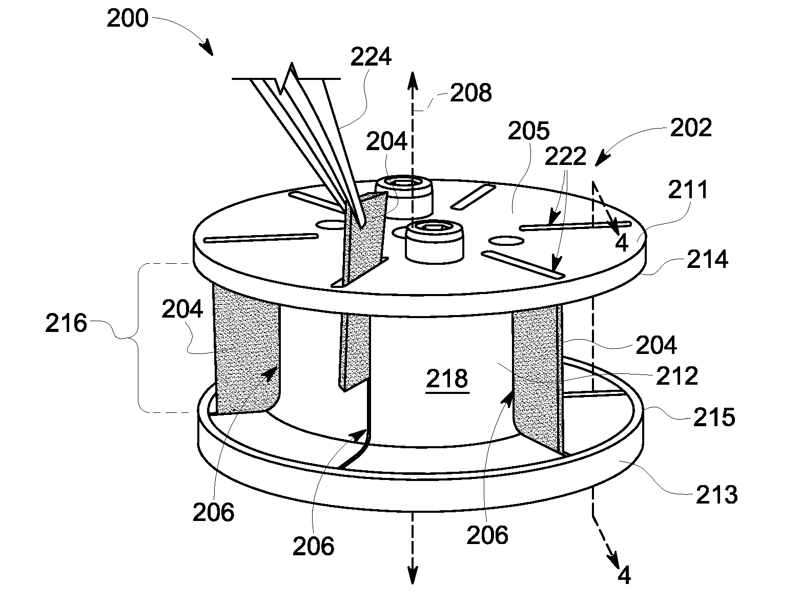
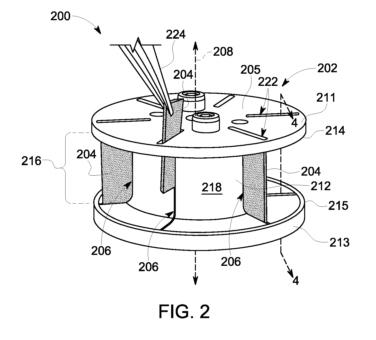
[0020]Embodiments described herein include isotope productions systems, particle accelerators, and extraction systems or devices of the same. Particular embodiments include foil holders that may be used with extraction systems of a particle accelerator. The foil holder may be configured to retain one or more extraction foils that are used to strip electrons from charged particles. The foil holder may retain the extraction foils within positioning slots. The extraction foils in some embodiments may not be tightly gripped or clamped by the foil holder thereby reducing unwanted stresses on the extraction foil. The extraction foil may be positioned by the foil holder to extend across a path taken by charged particles during operation of the particle accelerator so that the charged particles are incident on the extraction foil. During the stripping process, thermal energy may be generated within the extraction foil causing the extraction foil to change size and / or shape. Embodiments desc...


PUM


Abstract

A particle accelerator including an electrical field system and a magnetic field system that are configured to direct a particle beam of charged particles along a designated path within an acceleration chamber. The particle accelerator also includes a foil holder having a beam window and a positioning slot that at least partially surrounds the beam window. The positioning slot is dimensioned to hold an extraction foil such that the extraction foil extends across the beam window and into the path of the charged particles. The positioning slot is defined by interior reference surfaces that face the extraction foil and retain the extraction foil within the positioning slot. The reference surfaces permit the extraction foil to move relative to the reference surfaces when the particle beam is incident on the extraction foil.

Description

BACKGROUND OF THE INVENTION[0001]Various embodiments described herein relate generally to particle accelerators, and more particularly to particle accelerators having extraction foils for stripping electrons from charged particles.[0002]Particle accelerators, such as cyclotrons, may have various industrial, medical, and research applications. For example, particle accelerators may be used to produce radioisotopes (also called radionuclides), which have uses in medical therapy, imaging, and research, as well as other applications that are not medically related. Systems that produce radioisotopes typically include a cyclotron that has a magnet yoke surrounding an acceleration chamber. The cyclotron may include opposing pole tops that are spaced apart from each other. Electrical and magnetic fields may be generated within the acceleration chamber to accelerate and guide charged particles along a spiral-like orbit between the poles. To produce the radioisotopes, the cyclotron forms a pa...

Claims


Application Information

Patent Timeline
Patent Type & Authority Applications(United States)
IPC IPC(8): H05H7/10H05H13/00
CPCH05H13/005H05H7/10
Inventor SVEDBERG, OSKARERIKSSON, TOMASNORLING, JONAS OVEASKEBRO, PETER
Owner GENERAL ELECTRIC CO
Why Eureka
Try Eureka