Time signal generator and time signal generating method

a time signal and time signal technology, applied in the direction of electric variable regulation, process and machine control, instruments, etc., can solve the problems of unstable oscillation of output voltage vout, and achieve the effect of improving the response speed of power converter and increasing the transient response speed

Active Publication Date: 2015-03-19
UPI SEMICON CORP
View PDF8 Cites 9 Cited by
  • Summary
  • Abstract
  • Description
  • Claims
  • Application Information

AI Technical Summary

Benefits of technology

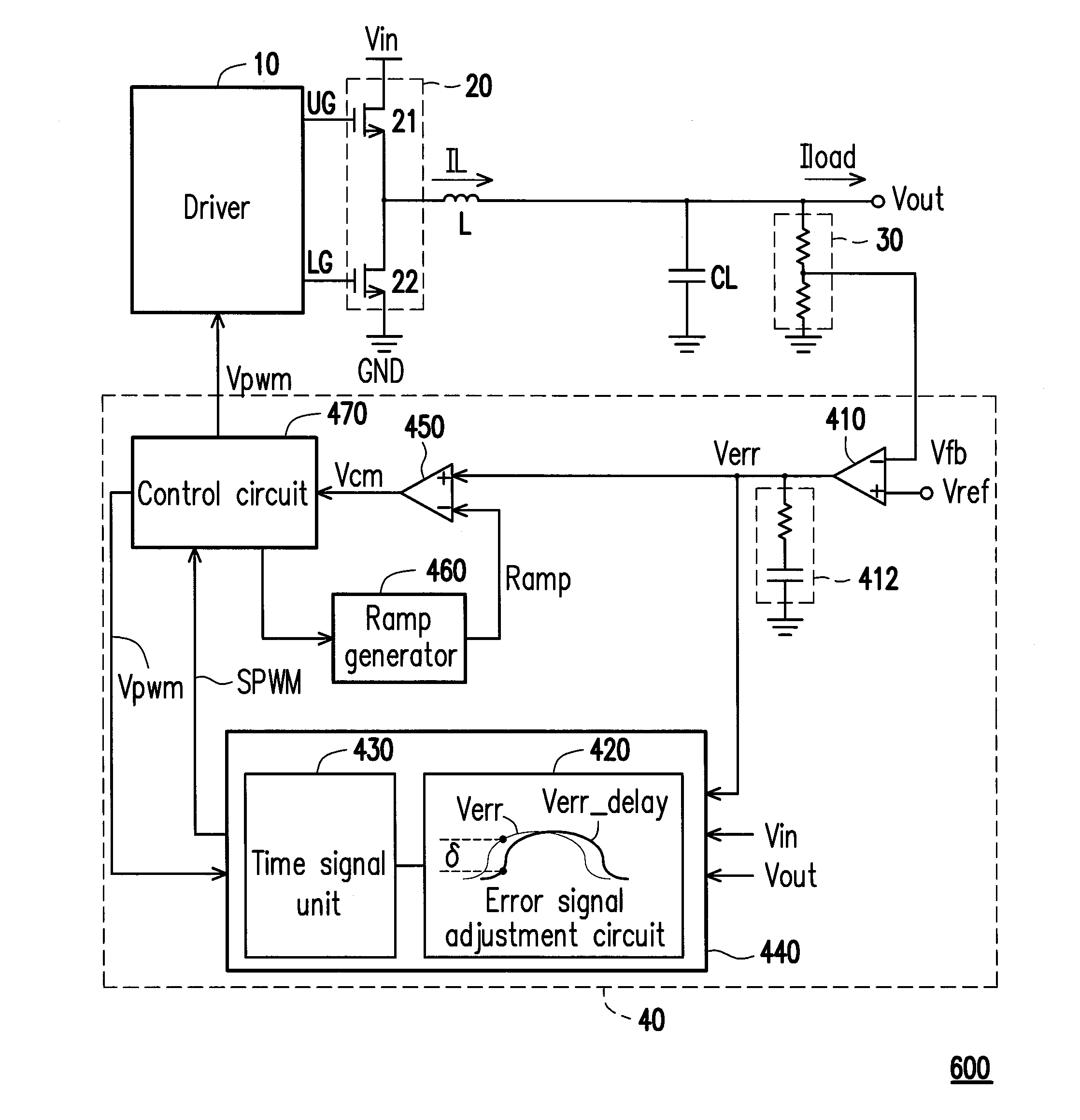
[0028]According to the above descriptions, in the time signal generator and the time signal generating method of the invention, the time signal is generated according to the error signal and the error delay signal, so as to change a length of on time in response to the load transient variation. The time signal can serve to improve a response speed of the power converter, such that the output voltage is quickly returned to a stable state and the transient response speed is increased.

Problems solved by technology

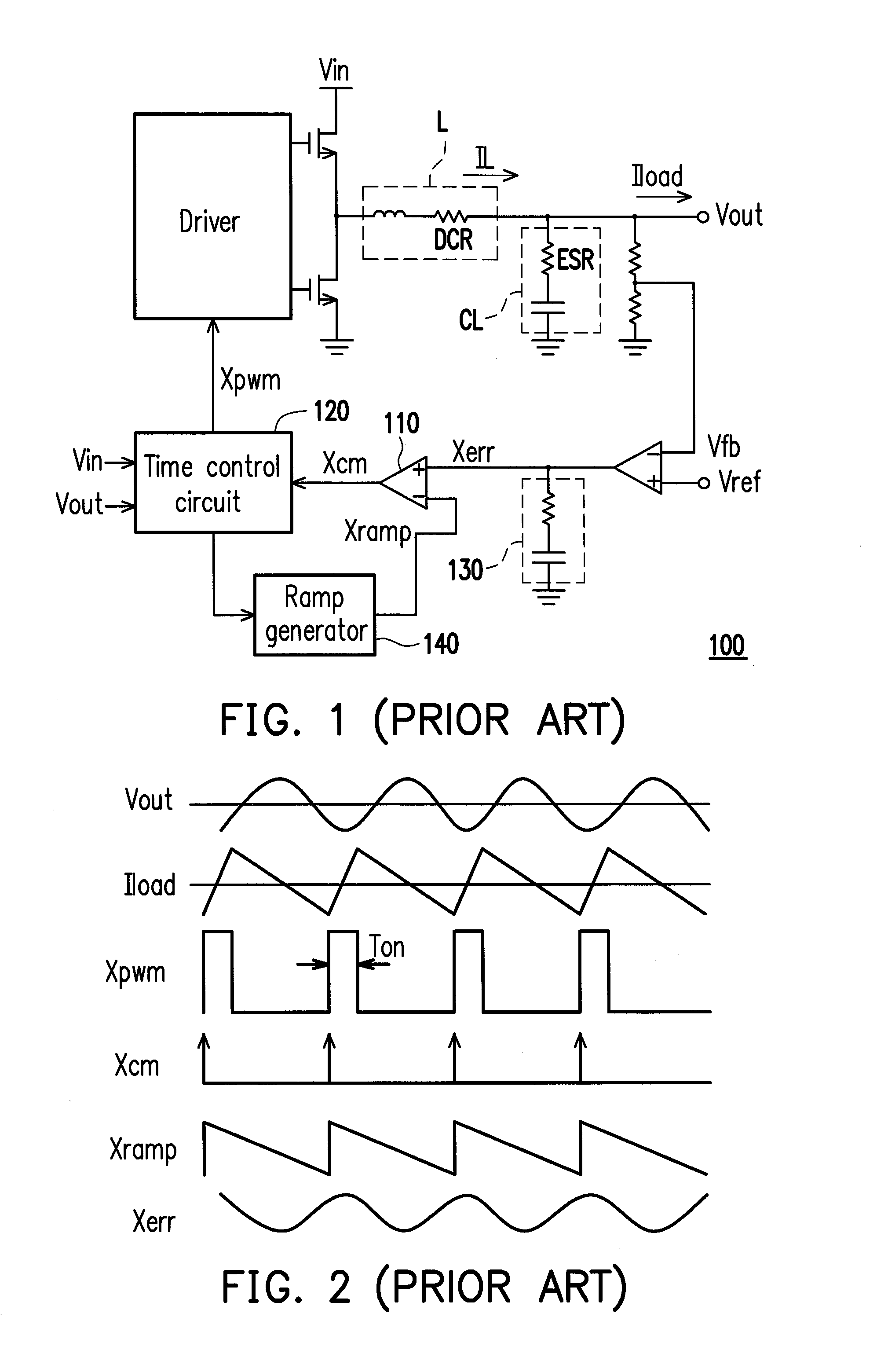
The above reasons lead to unstable oscillation of the output voltage Vout of the power converter 100.
As shown in FIG. 1, when an equivalent series resistance ESR of a regulation capacitor CL and an equivalent series resistance DCR of an inductor L at an output terminal are all very small, the original error signal Xerr generated by the compensation circuit 130 cannot provide enough stability to the loop, which may cause unstable oscillation of the output voltage Vout.

Method used


Image

  • Time signal generator and time signal generating method
  • Time signal generator and time signal generating method
  • Time signal generator and time signal generating method

Examples


first embodiment

[0052]FIG. 7 is a circuit schematic diagram of the time signal generator according to the invention. Referring to FIG. 7, the time signal generator 440A includes an error signal adjustment circuit 420A and a time signal unit 430A. The error signal adjustment circuit 420A includes an input unit 422, a delay unit 423 and a conversion control device 424. The time signal unit 430A is configured to provide the time signal SPWM. The delay unit 423 includes a resistor Rdelay and a capacitor Cdelay. The delay unit 423 is coupled to the input unit 422, and generates the error delay signal Verr_delay according to the error signal Verr. The conversion control device 424 is coupled to the input unit 422, the delay unit 423 and the time signal unit 430A, and controls the time signal unit 430A to generate the time signal SPWM according to the error signal Verr and the error delay signal Verr_delay.

[0053]A first input terminal of the input unit 422 receives the error signal Verr. A first terminal ...

second embodiment

[0063]FIG. 9 is a circuit schematic diagram of the time signal generator according to the invention. Referring to FIG. 9, the time signal generator 440B includes an error signal adjustment circuit 420B and a time signal unit 430B. The error signal adjustment circuit 420B includes an input unit 422, a delay unit 423 and a conversion control device 426. The time signal unit 430B is configured to provide the time signal SPWM. The delay unit 423 includes a resistor Rdelay and a capacitor Cdelay. The delay unit 423 is coupled to the input unit 422, and generates the error delay signal Verr_delay according to the error signal Verr. The conversion control device 426 is coupled to the input unit 422, the delay unit 423 and the time signal unit 430B, and controls the time signal unit 430B to generate the time signal SPWM according to the error signal Verr and the error delay signal Verr_delay.

[0064]A first input terminal of the input unit 422 receives the error signal Verr. A first terminal ...


PUM


Abstract

A time signal generator and a time generating method used in a power converter are provided. The time generating method includes following steps. An error delay signal is generated according to an error signal, wherein the error signal is related to an output voltage of the power converter. A time signal is generated according to the error signal and the error delay signal. The time signal may serve to improve a response speed of the power converter.

Description

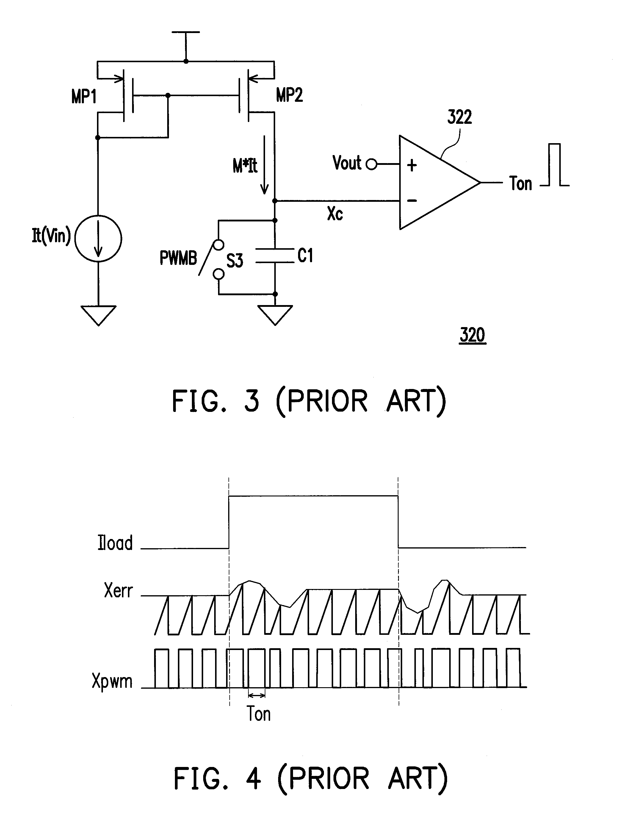
CROSS-REFERENCE TO RELATED APPLICATION[0001]This application claims the priority benefit of Taiwan application serial no. 102133716, filed on Sep. 17, 2013. The entirety of the above-mentioned patent application is hereby incorporated by reference herein and made a part of this specification.BACKGROUND[0002]1. Technical Field[0003]The invention relates to a power conversion technique. Particularly, the invention relates to a time signal generator adapted to a power converter and a time signal generating method.[0004]2. Related Art[0005]FIG. 1 is a schematic diagram of a conventional power converter. FIG. 2 is a waveform diagram of the conventional power converter. Referring to FIG. 1 and FIG. 2, the conventional power converter 100 generally adopts a constant on time architecture. A ramp generator 140 generates a ramp signal Xramp having a constant triangular wave. A comparator 110 compares an error signal Xerr with the ramp signal Xramp to generate a comparison signal Xcm. A time c...

Claims


Application Information

Patent Timeline
Patent Type & Authority Applications(United States)
IPC IPC(8): H02M3/158
CPCH02M3/158H02M3/156H02M3/1588H02M1/0025H02M3/1566Y02B70/10
Inventor CHEN, YA-PING
Owner UPI SEMICON CORP
Why Eureka
Try Eureka