
Printing apparatus and printing method

a printing apparatus and printing method technology, applied in the field of printing apparatus and printing method, can solve the problems of density unevenness, density unevenness is generated, cockling unevenness, etc., and achieve the effect of suppressing density unevenness and suppressing dots bleeding

Inactive Publication Date: 2015-03-19
SEIKO EPSON CORP
View PDF1 Cites 6 Cited by
  • Summary
  • Abstract
  • Description
  • Claims
  • Application Information

AI Technical Summary

Benefits of technology

The present invention aims to solve the problem of cockling and its impact on image quality in inkjet printing. By using a certain amount of ink and reducing the amount of another ink that causes density unevenness, the invention effectively suppresses brightness reduction and reduces the impact of cockling on image quality. This reduction in bleeding and density unevenness allows the invention to be applied without compromising the relationship between color input values and ink amounts. Additionally, the invention allows for a reduction in the amount of ink applied without exceeding the amount that can be applied to the print substrate, resulting in reduced bleeding and density unevenness.

Problems solved by technology

Changes in the coverage ratio cause so-called density unevenness.
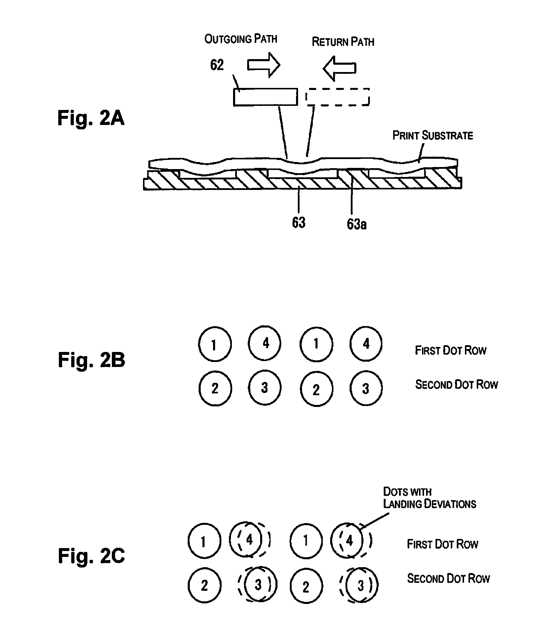
In addition, a phenomenon where density unevenness is generated due to the print substrate changing shape in this manner is described as cockling unevenness.
Since deterioration in image quality which is caused by cockling is a problem which has been remarkable in recent years, effective solutions have not yet been proposed.
As a result, an increase in brightness due to the dots of the second ink is reduced even in a case where dots of the first ink cause density unevenness (cackling unevenness) due to cockling.
Then, it is difficult to select the amount of ink for the first ink where it is easy for density unevenness to be generated according to the range of the input values being narrowed.

Method used


Image

  • Printing apparatus and printing method
  • Printing apparatus and printing method
  • Printing apparatus and printing method

Examples


first embodiment

1. First Embodiment

1.1. Configuration of Print Control Apparatus

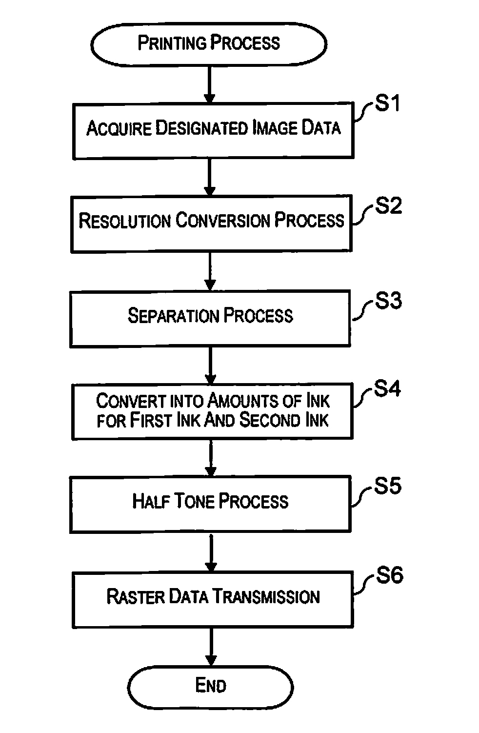
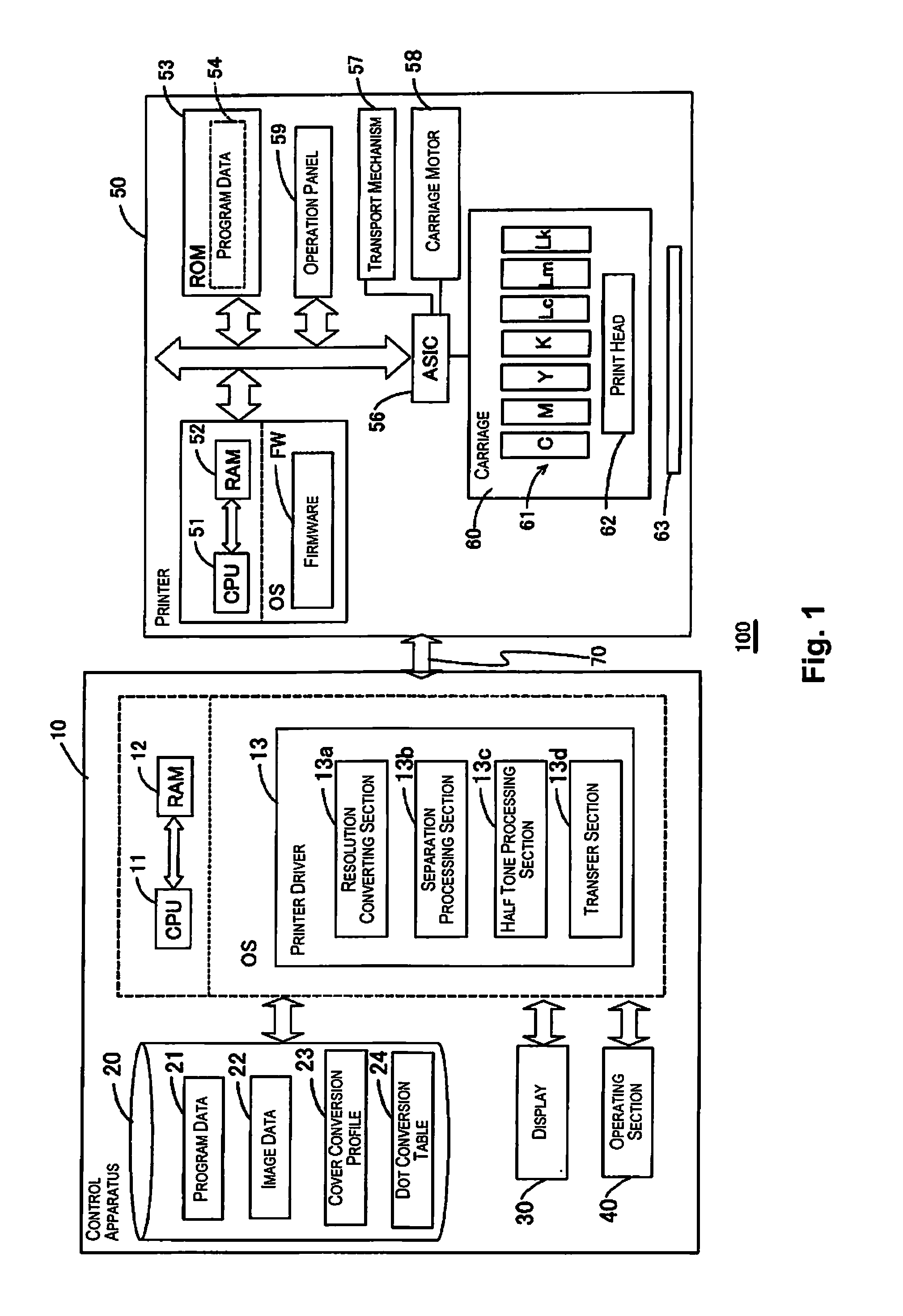
[0038]FIG. 1 schematically illustrates a hardware configuration and a software configuration according to the illustrated embodiment. FIG. 1 illustrates a control apparatus 10 and a printer 50. The control apparatus 10 has a function of executing printing in the printer 50 by controlling the printer 50 and corresponds to, for example, a personal computer (a PC), a server, a mobile terminal apparatus, or the like. The printer 50 is an output apparatus (JIS X0012-1990) which creates a hard copy recording of data with rows of discrete graphic characters, which belong to one or a plurality of character collections which are determined in advance, as the main format. In many cases, it is also possible to use the printer as a plotter. A plotter is an output apparatus (JIS X0012-1990) which directly produces a hard copy recording of data in the format of two-dimensional graphics on a medium which is able to be removed. It is s...

second embodiment

2. Second Embodiment

[0092]In a second embodiment, an ink with a high brightness compared to the first ink is used as the second ink, but the second embodiment is different to the first embodiment in the configuration where the first ink and the second ink are not the same color. As a result, in the second embodiment, in a case where the first ink is any of cyan, magenta, and black, the second ink is any of light cyan (Lc), light magenta (Lm), gray (Lk), and yellow (Y). It is obvious that the relationship characteristics between the first ink and the second ink are not limited to this as long as there is a difference in brightness.

[0093]FIGS. 11A and 11B are diagrams explaining a separation process according to the second embodiment. In FIG. 11A, the first ink is cyan (C) and the second ink is yellow (Y). That is, the second embodiment is the same as the first embodiment in the configuration where the dots of the first ink and the dots of the second ink are formed at positions which ...

modified example 1

[0102]The countermeasure for cockling unevenness in the present application may be applied only with regard to print substrate where it is easy for cockling to occur. For example, range coated paper (RC paper) is known to have low water absorption. On the other hand, normal paper and cardboard are known to have high water absorption and for it to be easy for cockling to occur compared to range coated paper. As a result, the printing apparatus 100 may use the dot conversion table 24 for a countermeasure for cockling unevenness only in a case of using the print substrate such as cardboard where it is easy for cockling to occur.

[0103]By setting the configuration described above, since the cockling countermeasure of the present application is performed only in a case of using the print substrate where it is easy for cockling to occur, it is possible to prioritize the reproducibility of color in other cases.


PUM


Abstract

A printing apparatus includes a first processing section configured to convert input values that are specified for each pixel in image data into amounts of ink for inks of each color, and a second processing section configured to generate half tone data from the image data that is converted. The second processing section is further configured to convert an amount of ink for a first ink, which is in a range of a first amount of ink where it is easy for density unevenness to be generated, into an amount of ink for the first ink and an amount of ink for a second ink that is the same color as the first ink and has a high brightness compared to the first ink. An increase in the amount of the first ink that is set in the range of the first amount of ink is large.

Description

CROSS-REFERENCE TO RELATED APPLICATIONS[0001]This application claims priority to Japanese Patent Application No. 2013-194426 filed on Sep. 19, 2013. The entire disclosure of Japanese Patent Application No. 2013-194426 is hereby incorporated herein by reference.BACKGROUND[0002]1. Technical Field[0003]The present invention relates to a printing apparatus and a printing method where half tone dots are formed.[0004]2. Related Art[0005]There is known a printing method where half tone dots are printed by landing ink. Here, half tone data is an image which is configured by points which are different in the number of screen lines, size, shape, or density. Half tone data is generated by dithering, error diffusion, or the like. Half tone dots are individual elements which configure gradations. Half tone dots may take various shapes, such as square shapes, circle shapes, and oval shapes. Half tone dots are referred to below simply as dots.[0006]In addition, the image is an image which appropri...

Claims


Application Information

Patent Timeline
Patent Type & Authority Applications(United States)
IPC IPC(8): B41J2/175B41J2/21
CPCB41J2/21B41J2/17566B41J2/2056H04N1/52
Inventor KOBASHI, YUTAKA
Owner SEIKO EPSON CORP
Learn More