
Reducing Artifacts in an Image Data Set and X-Ray Device

a technology of image data and x-ray, applied in image data processing, diagnostics, applications, etc., can solve the problems of object giving rise to artifacts, concept cannot be used, and it is not possible to produce a complete and correct depiction of objects, so as to improve the depiction of objects

Active Publication Date: 2015-03-19
SIEMENS HEALTHCARE GMBH
View PDF2 Cites 17 Cited by
  • Summary
  • Abstract
  • Description
  • Claims
  • Application Information

AI Technical Summary

Benefits of technology

The patent aims to improve the quality of three-dimensional image data sets by reducing artifacts generated by objects outside the reconstruction volume. This way, the image quality can be improved.

Problems solved by technology

However, this concept cannot be used if the object giving rise to the artifacts does not appear in the reconstruction volume (nominal measuring field).
The reconstruction volume is the area that is ultimately also to be reconstructed in the image data set while the projection data is not complete for all objects and structures outside the reconstruction volume so that it is also not possible to produce a complete and correct depiction of the objects.
Even if only a few projection images represent the object, it is still possible for the object to give rise to artifacts.
To date, there has been no practicable solution for effective artifact correction where an object is located outside the reconstruction volume.
These methods also do not produce satisfactory results when the objects are only visible in a few projection images.

Method used


Image

  • Reducing Artifacts in an Image Data Set and X-Ray Device
  • Reducing Artifacts in an Image Data Set and X-Ray Device
  • Reducing Artifacts in an Image Data Set and X-Ray Device

Examples


first embodiment

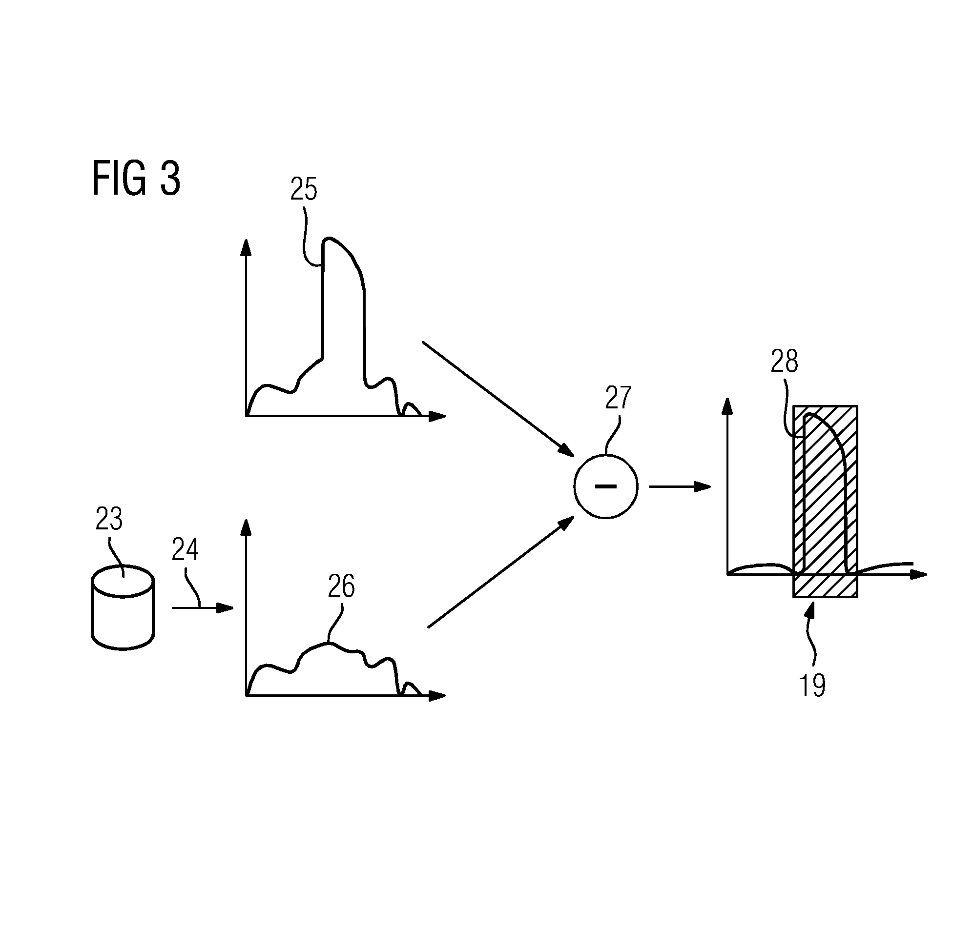
[0048]The procedure according to FIG. 3 may be further improved in the first embodiment in that the reconstruction data set 23 undergoes segmentation, preferably four-material segmentation according to the material classes air, bone, soft tissue and contrast medium. From the segmentation, a virtual, normalization image based on the effective transmission lengths of the material classes is determined. This normalization image may be used to normalize the measured projection images 14, 18 and the comparative images so that smoothing of the other deviating portions occurs and the method becomes more robust.

second embodiment

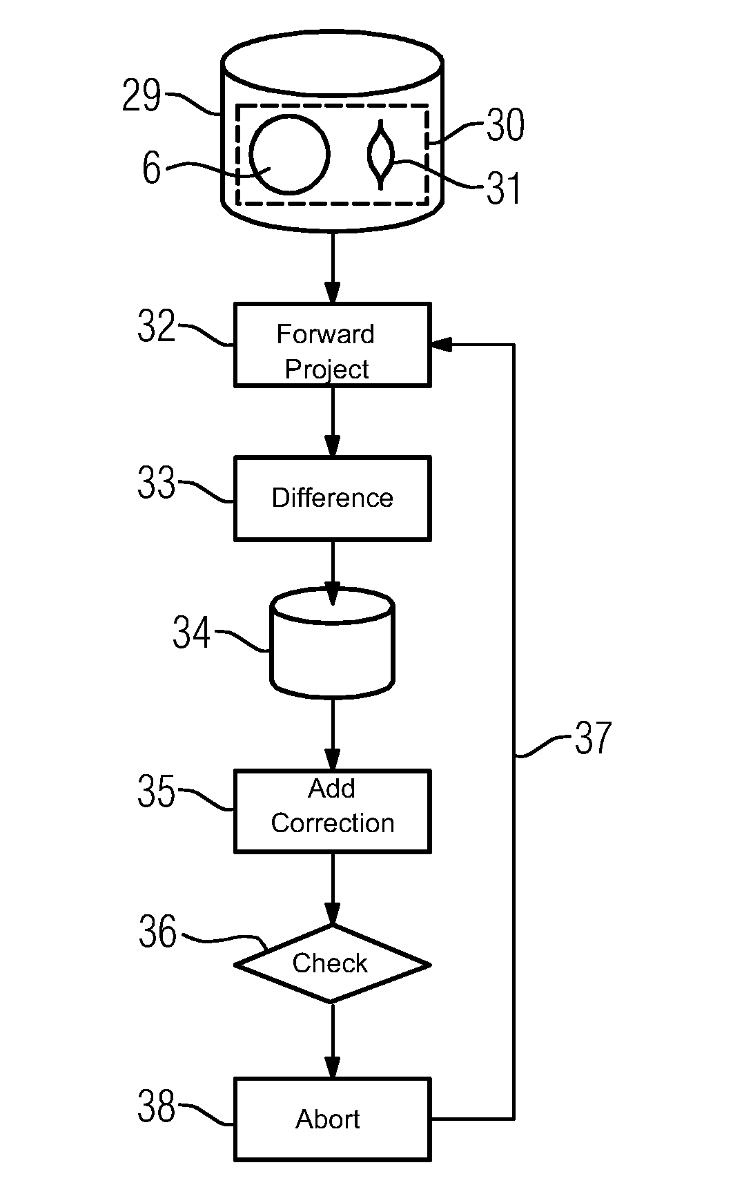
[0049]In the second embodiment, which is explained in more detail by FIG. 4, the localization of the areas 19 takes place within the context of an iterative, constantly improving reconstruction of the object 7 as well. To this end, an iterative procedure is used wherein a reconstruction data set is generated from the measured projection images 14, 18, although it relates to an enlarged object volume 30, which is indicated schematically in FIG. 4. The object volume 30 includes the reconstruction volume 6 and also an area that contains the object 7. As the area of the object 7 is not covered sufficiently in order to obtain a complete reconstruction since the object 7 may only be seen in some of the measured projection images 14, 18, the depiction 31 of the object 7 in the reconstruction data set 29 is imprecise, for example blurred, as indicated in FIG. 4.

[0050]It is now the object to improve the reconstruction data set 29 iteratively, for which, in an act 32, first comparative images...


PUM


Abstract

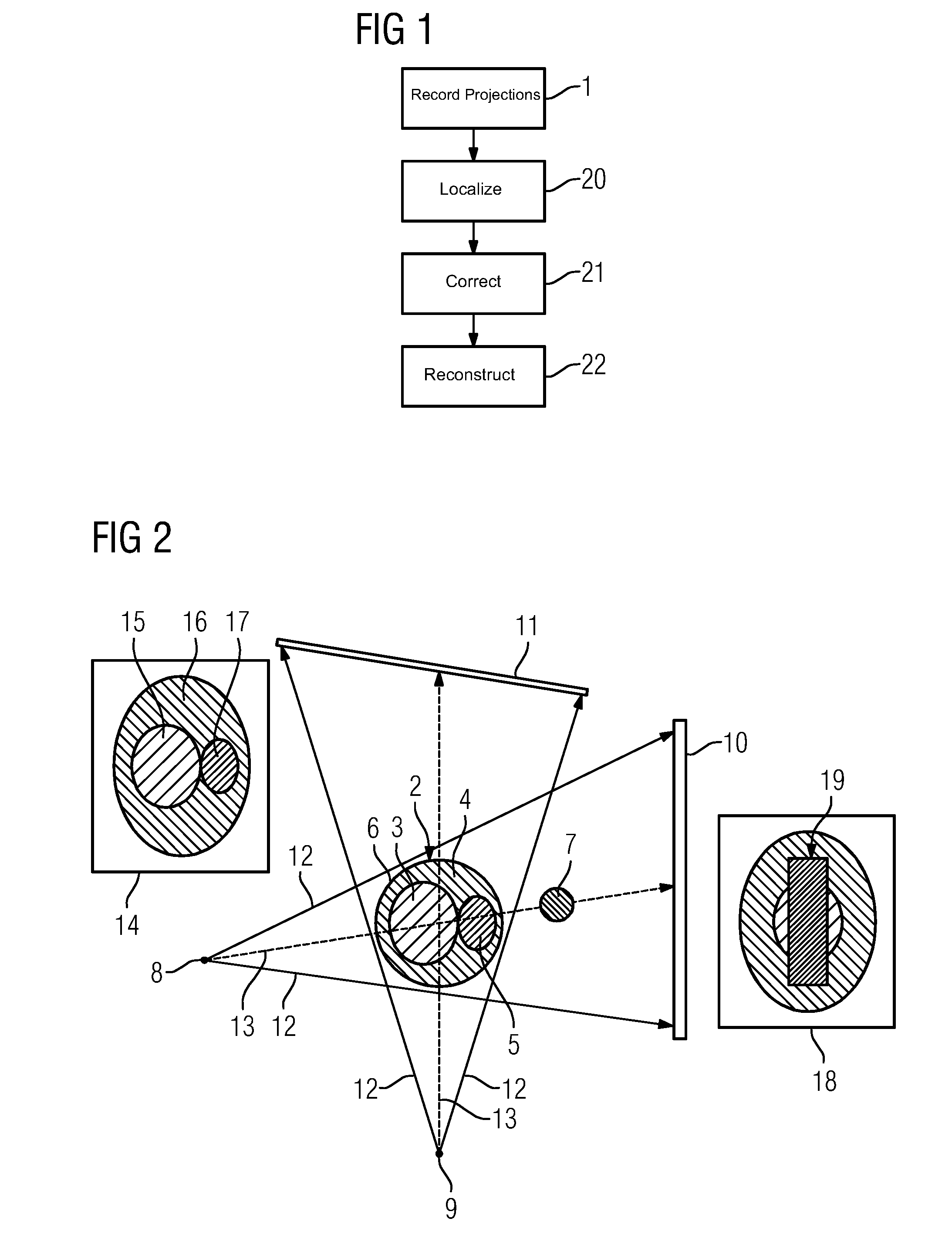
Streak artifacts generated by at least one X-ray attenuating object arranged outside a reconstruction volume in a three-dimensional image data set showing the reconstruction volume are reduced. The reconstruction volume is reconstructed from two-dimensional projection images recorded from different projection directions. The object is localized in the projection images showing the object. To determine corrected projection images for the reconstruction of the image data set, the image data of the area of each projection image showing the object is corrected to remove the object. The localization of the object is performed taking into account difference images of the measured projection images and from a reconstruction data set of forward-projected comparative images reconstructed from the measured projection images.

Description

RELATED CASE[0001]This application claims the benefit of DE 102013218819.6, filed on Sep. 19, 2013, which is hereby incorporated by reference in its entirety.TECHNICAL FIELD[0002]The present embodiments relate to reducing artifacts generated by at least one X-ray attenuating object arranged outside a reconstruction volume in a three-dimensional image data set.BACKGROUND[0003]Artifacts in image data sets recorded with X-rays that are reconstructed from projection images may originate in objects of higher density lying inside or outside the reconstruction volume. Objects of this kind generally have a higher density and / or a higher attenuation coefficient than naturally occurring materials in the body of a person, which is usually recorded as the object under examination. Such artifacts are particularly frequently artifacts resulting from metal objects and so may also be designated metal artifacts.[0004]To date, a plurality of methods have been suggested for correcting or avoiding meta...

Claims


Application Information

Patent Timeline
IPC IPC(8): A61B6/00G06T5/50G06T11/00G06T7/00A61B6/03G06T5/00
CPCA61B6/5258A61B6/032A61B6/4085A61B6/505G06T5/002G06T11/008G06T2207/30008G06T7/0097G06T5/50G06T2207/10081G06T2207/20061G06T2207/20224G06T7/0083A61B6/4441G06T7/12G06T7/174G06T5/70
Inventor KYRIAKOU, YIANNIS
Owner SIEMENS HEALTHCARE GMBH
Learn More