Acoustic transducer and microphone

a technology of acoustic transducer and microphone, which is applied in the direction of electrostatic transducer microphone, mic, and semiconductor devices, etc., can solve the problems of poor damage resistance of acoustic sensors, lack of design flexibility, and risk of diaphragm and back plate becoming damaged or cracked, so as to suppress the deformation of the vibrating electrode plate (diaphragm) and avoid the concentration of stress and damage

Active Publication Date: 2015-03-19
MMI SEMICON CO LTD
View PDF9 Cites 52 Cited by
  • Summary
  • Abstract
  • Description
  • Claims
  • Application Information

AI Technical Summary

Benefits of technology

[0014]One or more embodiments of the present invention provides an acoustic transducer that can maintain the frequency characteristics in acoustic vibration detection while also being able to avoid the co

Problems solved by technology

As a result, there are cases where the diaphragm 14 and the back plate 16 become damaged or cracked due to undergoing large deformation, and the damage resistance of the acoustic sensor 11 is poor.
Even with an acoustic sensor structured as disclosed in U.S. Pat. No. 6,535,460, the acoustic resistance is high in order to maintain the frequency characteristics, that is to say pressure is not likely to escape, and therefore when a large degree of pressure is applied to the diaphragm, a phenomenon such as that shown in FIGS. 1B and 1C occurs, and there is the risk of the diaphragm and back plate becoming damaged or cracked.
However, with the acoustic sensor disclosed in U.S. Pat. No. 8,111,871, a spring suited to detecting acoustic vibration and a spring suited to allowing air pressure to escape cannot be designed independently, and there is a lack of flexibility in terms of d

Method used


Image

  • Acoustic transducer and microphone
  • Acoustic transducer and microphone
  • Acoustic transducer and microphone

Examples


embodiment 1

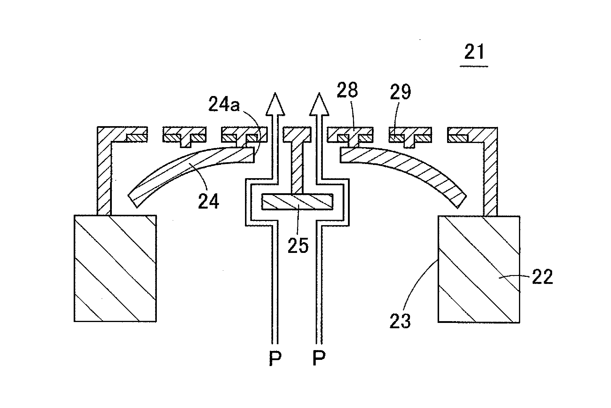
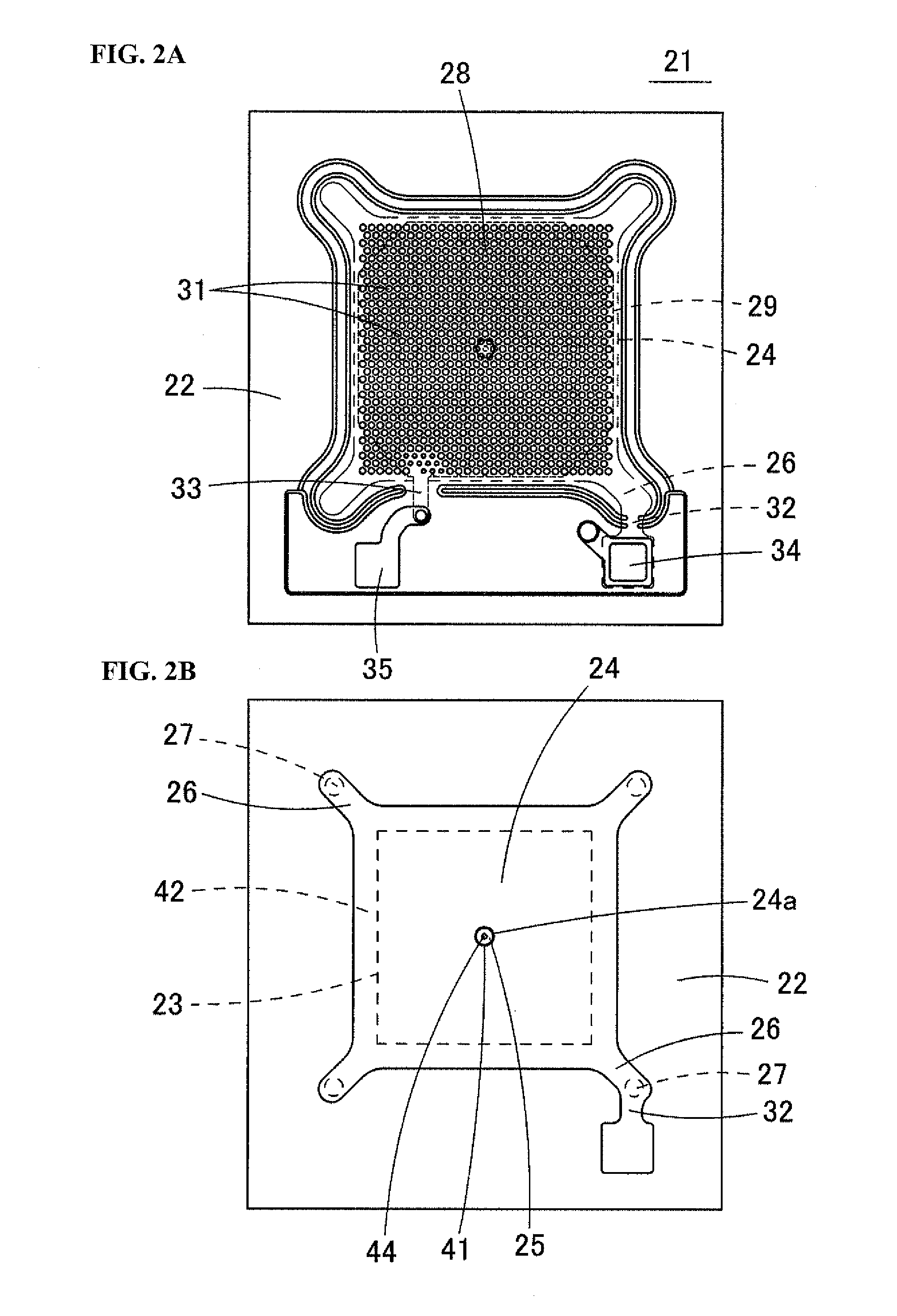
[0055]The following describes an acoustic transducer according to Embodiment 1 of the present invention, that is to say an acoustic sensor 21, with reference to the drawings. FIG. 2A is a plan view of the acoustic sensor 21 according to Embodiment 1 of the present invention. FIG. 2B is a plan view of a state in which a diaphragm 24 is exposed by removing a back plate 28 and a fixed electrode plate 29 from the acoustic sensor 21 shown in FIG. 2A. FIG. 3 is a cross-sectional diagram of the acoustic sensor 21.

[0056]The acoustic sensor 21 is a capacitance type of device created using MEMS technology. As shown in FIG. 3, in the acoustic sensor 21, the diaphragm 24 (vibrating electrode plate) is provided on a substrate 22, which is made of a silicon substrate or the like, via anchors 27, and the fixed electrode plate 29 is provided above the diaphragm 24 in opposition to the diaphragm 24.

[0057]A rectangular cavity 23 is formed in the substrate 22 so as to pass from the upper surface to th...

embodiment 2

[0082]FIG. 7A is a schematic cross-sectional diagram showing an acoustic sensor 51 according to Embodiment 2 of the present invention. FIG. 7B is a plan view showing an enlargement of the central portion of a back plate 28 of the acoustic sensor 51.

[0083]In the acoustic sensor 51, multiple support portions 44 extend downward from the central portion of the lower surface of the back plate 28, and the regulation portion 25 is supported by these support portions 44. If the regulation portion 25 is supported by multiple support portions 44, the rigidity of the regulation portion 25 increases, and the regulation portion 25 is not likely to undergo deformation even when subjected to a large degree of pressure, thus making it possible to prevent a reduction in the distance between the edge of regulation portion 25 and the edge of the opening 24a of the deformed diaphragm 24.

[0084]Remarks Regarding Variations

[0085]Although the opening 24a and the regulation portion 25 are circular in one or...

embodiment 3

[0088]FIG. 10 is a cross-sectional diagram showing an acoustic sensor 61 according to Embodiment 3 of the present invention, a feature of which is that the diaphragm 24 is provided above the fixed electrode plate 29. In the acoustic sensor 61, a flat plate-shaped back plate 28 is provided on the upper surface of the substrate 22 via an insulation layer 62. The fixed electrode plate 29 is formed on the upper surface of the back plate 28. Multiple acoustic holes 31 are formed in the back plate 28 and the fixed electrode plate 29 above the cavity 23. Also, the diaphragm 24 is arranged so as to oppose the fixed electrode plate 29 above the back plate 28. Leg pieces 26 extending from the diaphragm 24 are supported by anchors 27 provided on the upper surface of the back plate 28.

[0089]The opening 24a is formed in the central portion of the diaphragm 24, and the regulation portion 25 is arranged inside the opening 24a. The regulation portion 25 is fixed to the upper edge of the support por...


PUM


Abstract

An acoustic transducer has a substrate having a cavity, a vibrating electrode plate disposed above the substrate and having a void portion that allows pressure to escape, a fixed electrode plate disposed above the substrate opposite the vibrating electrode plate, and a leak pressure regulation portion that hinders leakage of air pressure by passing through the void portion when the vibrating electrode plate is not undergoing deformation, and that becomes separated from the void portion and allows pressure to escape by passing through the void portion when the vibrating electrode plate undergoes deformation from being subjected to pressure.

Description

BACKGROUND[0001]1. Field[0002]The present invention relates to an acoustic transducer and a microphone. Specifically, the present invention relates to a capacitance type of acoustic transducer configured by a capacitor structure made up of a vibrating electrode plate (diaphragm) and a fixed electrode plate. The present invention also relates to a microphone that employs this acoustic transducer.[0003]2. Related Art[0004]FIG. 1A is a schematic diagram showing the structure of a conventional capacitance type of acoustic sensor (acoustic transducer). In an acoustic sensor 11 shown here, a cavity 13 is formed in a substrate 12 made up of a silicon substrate or the like, and a diaphragm 14 (vibrating electrode plate) is provided above the substrate 12 so as to cover the upper opening of the cavity 13. If the diaphragm 14 is rectangular, for example, the four corner portions thereof are supported on the upper surface of the substrate 12 by anchors 15. A dome-shaped back plate 16 is formed...

Claims


Application Information

Patent Timeline
IPC IPC(8): H04R19/04
CPCH04R19/04H04R19/005H01L2224/48091H01L2224/48137H01L2924/15151H01L2924/16152H01L2924/00014
Inventor UCHIDA, YUKI
Owner MMI SEMICON CO LTD
Why Eureka
Try Eureka