Composite module

a technology of composite modules and inductor elements, applied in the direction of printed circuit non-printed electric components association, high frequency circuit adaptation, wireless communication, etc., can solve the problems of stray capacitance and the like, frequency characteristics of inductor elements deterioration, characteristic impedance of wiring electrodes, etc., to prevent stray capacitance, produce more efficiently, and prevent stray capacitan

Active Publication Date: 2015-03-19
MURATA MFG CO LTD
View PDF5 Cites 4 Cited by
  • Summary
  • Abstract
  • Description
  • Claims
  • Application Information

AI Technical Summary

Benefits of technology

[0015]By doing so, stray capacitance is prevented from being produced, in other words, the stray capacitance is prevented from being produced more efficiently in comparison with a case in which the area of one cutout provided at a side closer to the wiring electrode is made larger than the area of the other cutout, when viewed from above.
[0016]It is preferable for the first ground electrode to be provided on the same surface where the wiring electrode is provided, for a third cutout to be provided in the first ground electrode at least at a portion of a region overlapping with the outer ground electrode when viewed from above, and for the wiring electrode to be provided in the third cutout. In this case, the wiring electrode and the first ground electrode are provided on the same surface, which makes it possible to dispose the electrodes on the wiring substrate at high density so as to miniaturize the composite module. In addition, because the wiring electrode is preferably provided in the third cutout overlapping with the outer ground electrode when viewed from above, the wiring electrode is shielded with certainty on the one main surface side of the wiring substrate.
[0017]According to various preferred embodiments of the present invention, the wiring electrode inside the wiring substrate overlaps with at least one of the first ground electrode and the outer ground electrode when viewed from above, and the first cutout is provided in the first ground electrode at least at a portion of a region overlapping with the wiring electrode and the outer ground electrode when viewed from above, such that stray capacitance produced between the wiring electrode and the first ground electrode is significantly reduced or prevented and impedance of the wiring electrode is adjusted by the first cutout while the wiring electrode is shielded with certainty on the one main surface side of the wiring substrate.

Problems solved by technology

However, when the electrodes are disposed close to one another as described above, undesired stray capacitance and the like are produced between the wiring electrodes and the ground electrodes constituting inductor elements, for example.
This causes a problem that frequency characteristics of the inductor elements are deteriorated and characteristic impedance of the wiring electrodes defined between the wiring electrodes and the ground electrodes cannot have a predetermined value.
This causes a risk that when the high frequency module 200 is mounted on a mother board, for example, signals leaked from other elements, modules, and so on formed on the mother board interfere with the inductor element 203 so that the frequency characteristics and the like of the high frequency module 200 are deteriorated.

Method used


Image

  • Composite module
  • Composite module
  • Composite module

Examples


second preferred embodiment

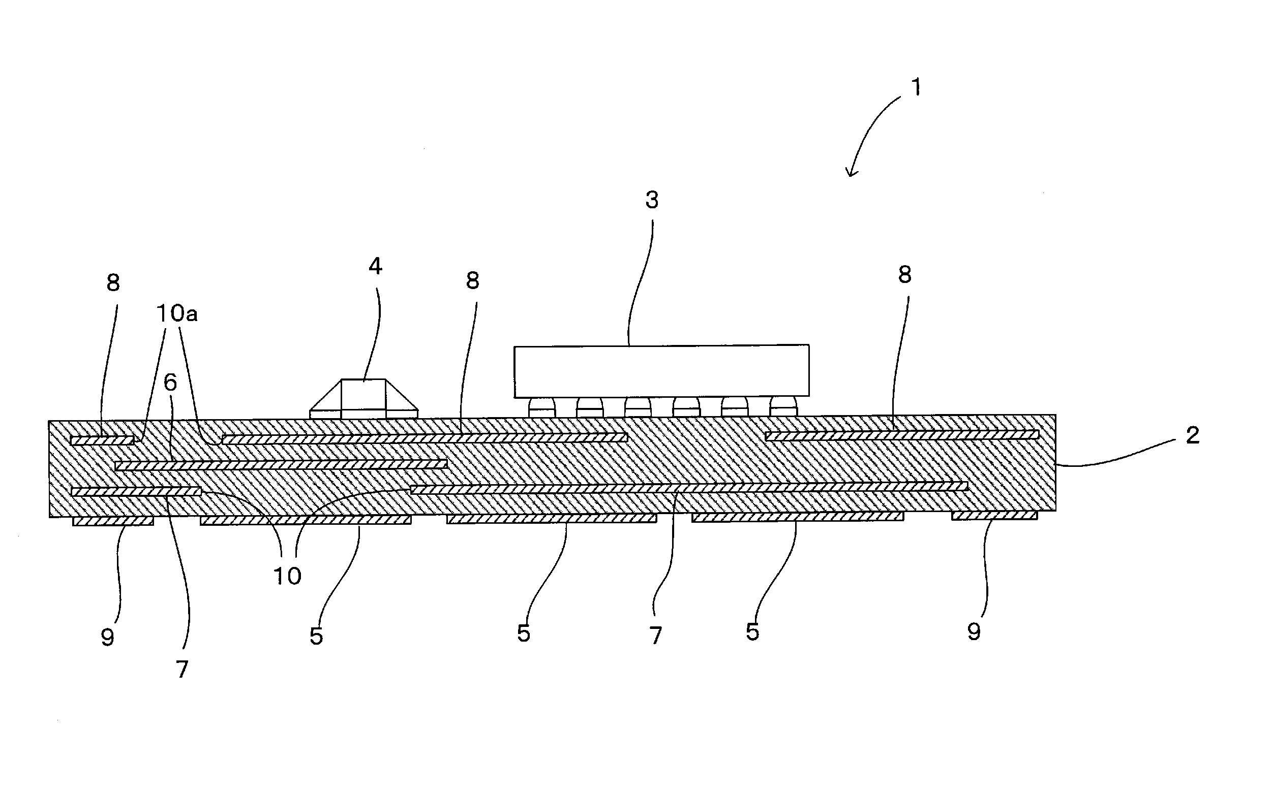
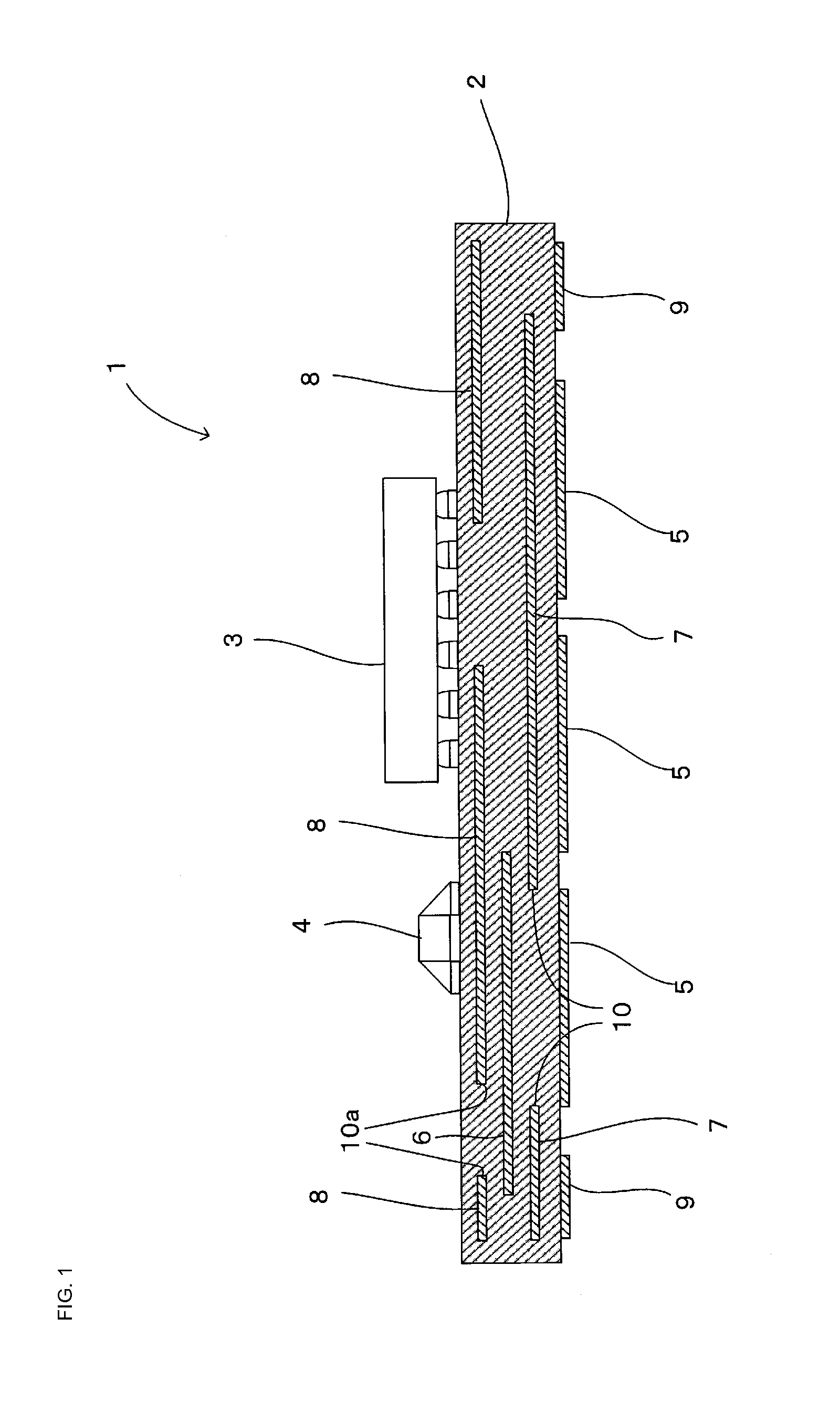
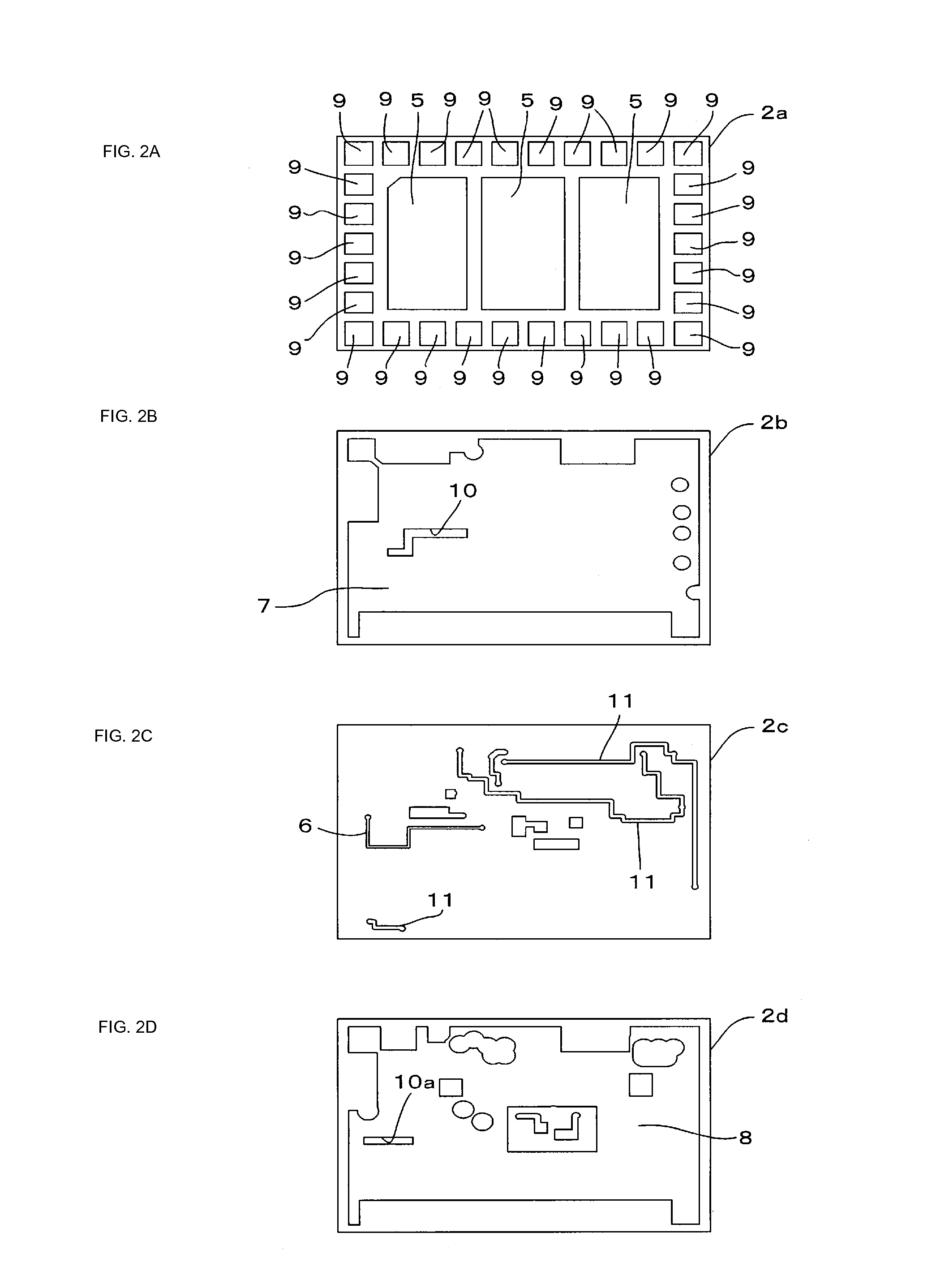
[0042]A composite module 1a according to a second preferred embodiment of the present invention will be described with reference to FIGS. 4A-4C. FIGS. 4A-4C include internal structure views showing a wiring substrate 12 in the composite module la, in which plan views of respective layers where the outer ground electrodes 5 of the wiring substrate 12, the first ground electrode 7, the wiring electrode 6, and so on are provided are illustrated.

[0043]The composite module 1a according to the present preferred embodiment differs from the composite module 1 of the first preferred embodiment having been discussed referring to FIGS. 1 and 2 in a point that the first ground electrode 7 and a portion 6a of the wiring electrode 6 both provided inside the wiring substrate 12 of the composite module 1a are provided on the same surface (a layer 12b being shared) while a remaining portion 6b of the wiring electrode 6 is provided on another layer 12c which is different from the layer 12b where the ...


PUM

PropertyMeasurementUnit
temperatureaaaaaaaaaa
areaaaaaaaaaaa
impedanceaaaaaaaaaa

Abstract

A composite module includes outer ground electrodes on one main surface of a wiring substrate, a wiring electrode inside the wiring substrate, and a first ground electrode between the wiring electrode and the outer ground electrode. A cutout is provided in the first ground electrode at least at a portion of a region overlapping with the wiring electrode and the outer ground electrode when viewed from above, and the wiring electrode overlaps with at least one of the first ground electrode and the outer ground electrode when viewed from above to reduce stray capacitance produced on the wiring electrode and to adjust impedance of the wiring electrode while preventing signals leaked from the exterior from interfering with the wiring electrode.

Description

BACKGROUND OF THE INVENTION[0001]1. Field of the Invention[0002]The present invention relates to composite modules provided with a wiring substrate including wiring electrodes provided inside and on a main surface thereof.[0003]2. Description of the Related Art[0004]With cellular phones becoming smaller in size and thickness, composite modules mounted therein are being required to be reduced in size and lowered in profile these days. As such, wiring substrates included in composite modules are made smaller in size and thickness, and various types of circuits are configured such that wiring electrodes, ground electrodes, and so on that constitute inductors, capacitors, and the like are so disposed as to be close to one another on each wiring substrate, whereby reduction in size and lowering in profile of the composite modules are realized. However, when the electrodes are disposed close to one another as described above, undesired stray capacitance and the like are produced between t...

Claims


Application Information

Patent Timeline
Patent Type & Authority Applications(United States)
IPC IPC(8): H05K1/02H05K1/16H05K1/18
CPCH05K1/0298H05K1/181H04W88/06H05K2201/10053H05K1/165H01L23/49822H01L23/49838H01L23/50H01L23/552H05K1/0225H05K1/0253H05K2201/09336H01L23/642H01L2224/16H01L2924/19105
Inventor KITAJIMA, HIROMICHI
Owner MURATA MFG CO LTD
Why Eureka
Try Eureka