Integration delayed optical feedback in image guidance

Active Publication Date: 2015-03-19
KONINKLJIJKE PHILIPS NV
View PDF4 Cites 10 Cited by
  • Summary
  • Abstract
  • Description
  • Claims
  • Application Information

AI Technical Summary

Benefits of technology

[0007]It would be advantageous to achieve a system where an image is displayed wherein both position of an instrument as well as tissue type is displayed. In general, the invention preferably seeks to mitigate, alleviate or eliminate one o

Problems solved by technology

In the images obtained this way, e.g. x-ray images or ultrasound images, it may be difficult, or even impossible, to accurately determine which type of tissue is present at the instrument, e.g. at tissue boundaries.
Obtaining tissue informatio

Method used


Image

  • Integration delayed optical feedback in image guidance
  • Integration delayed optical feedback in image guidance
  • Integration delayed optical feedback in image guidance

Examples


Example

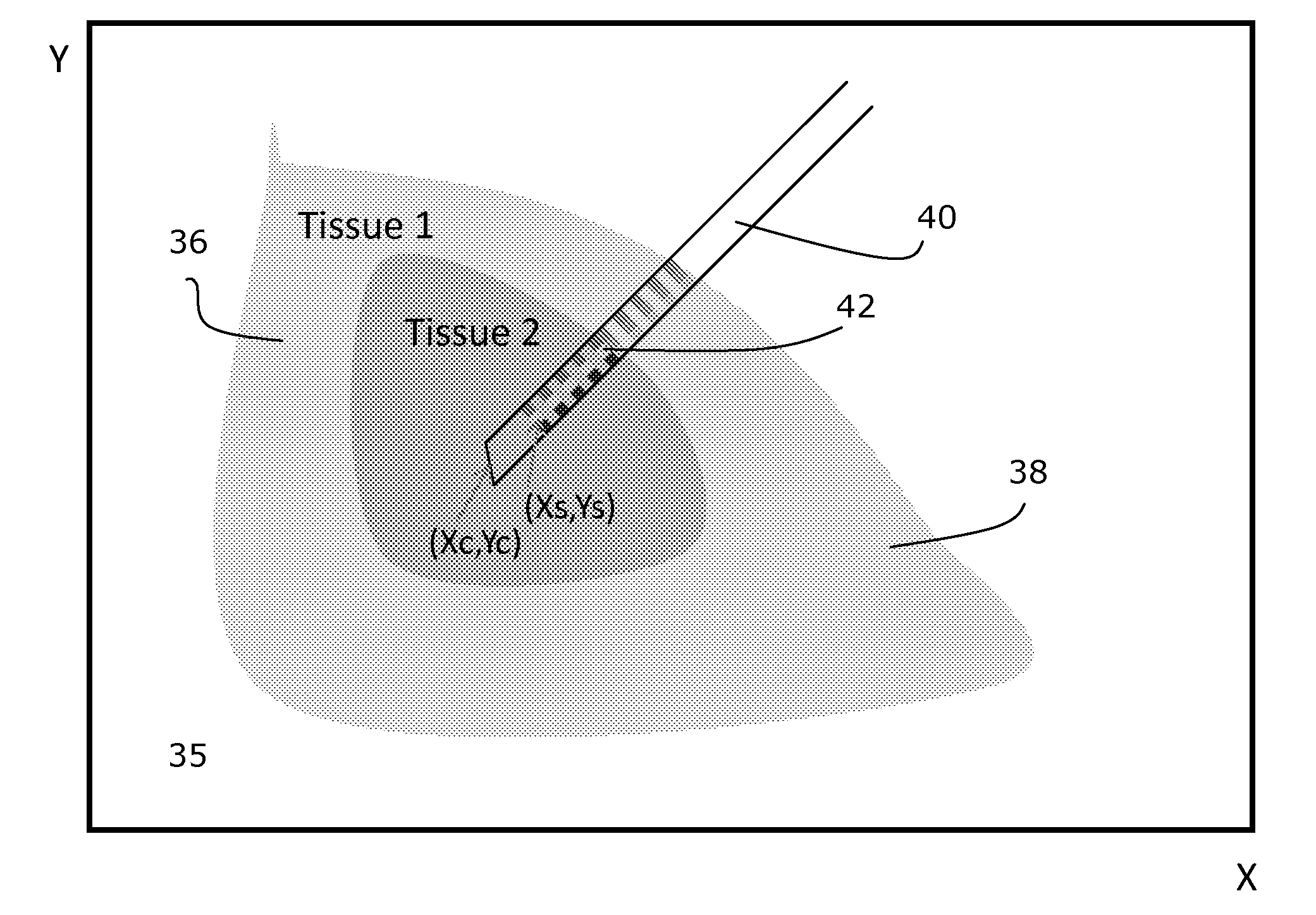
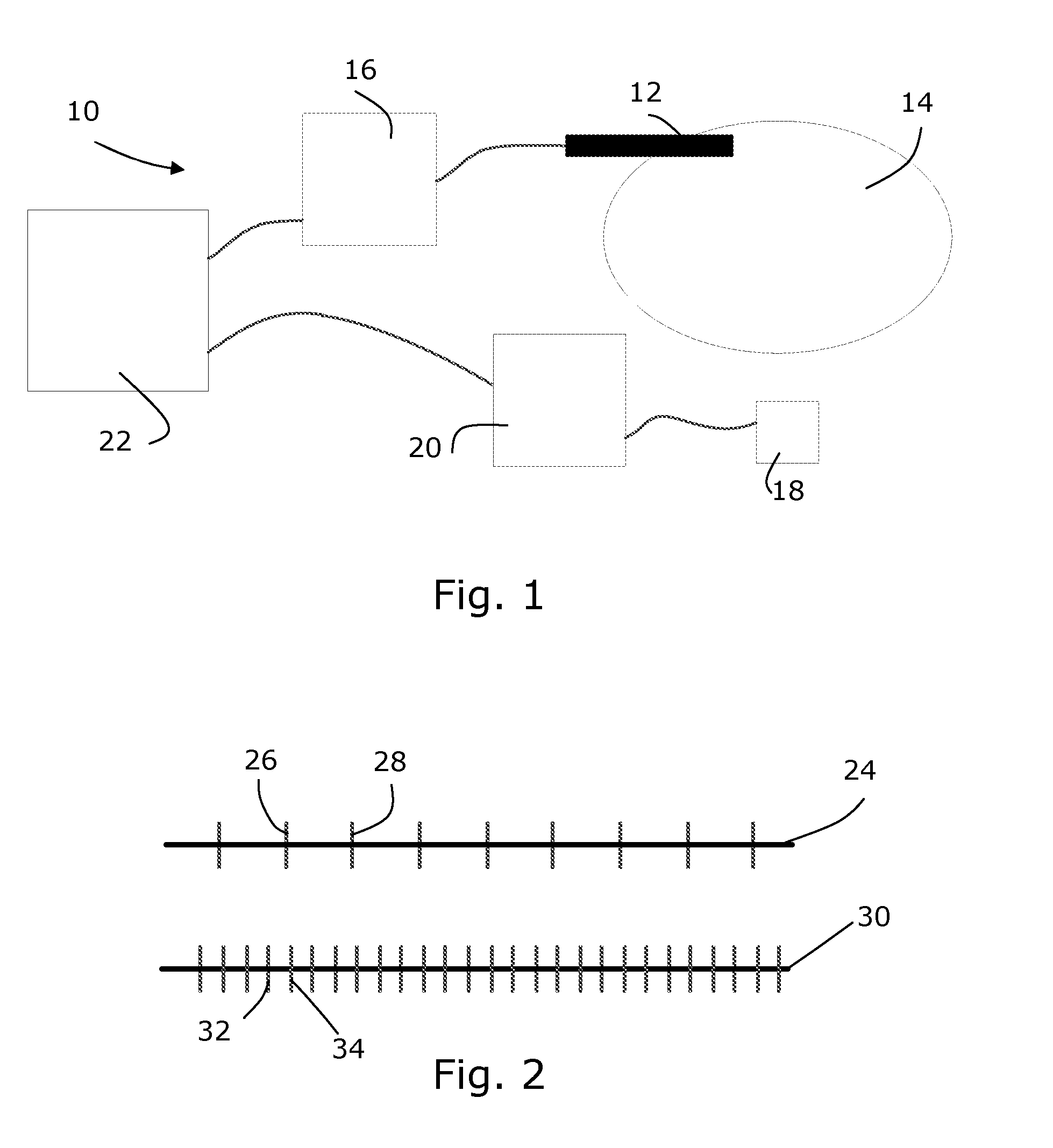
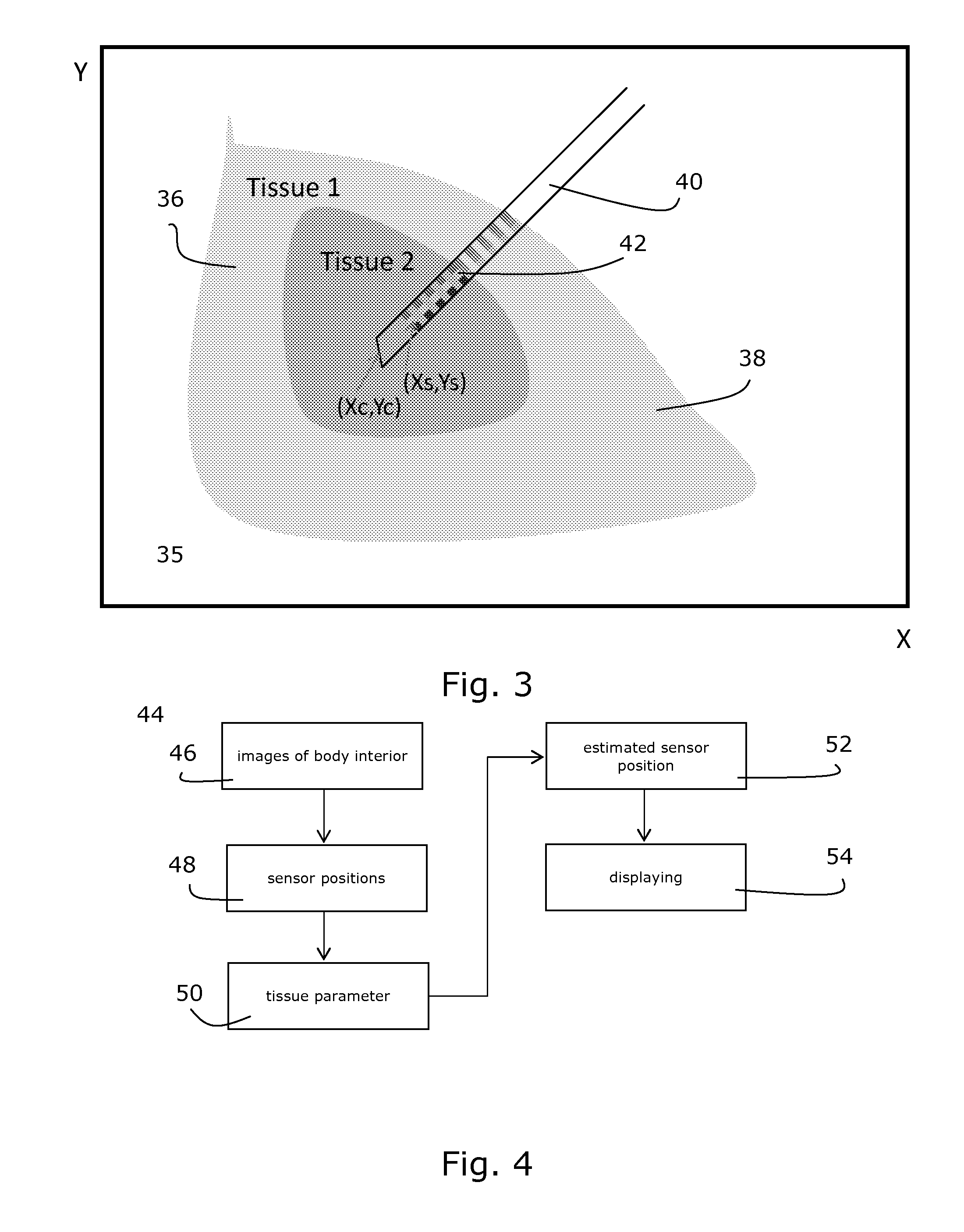
[0043]An embodiment of the invention is illustrated in FIG. 1 where a system 10 for navigating and positioning an instrument 12 in a body 14 is illustrated. The instrument 12 comprises a sensor, not illustrated here, for optical inspection of tissue in the body 14. The instrument 12 is configured to generate a tissue signal. The system 10 comprises a tissue-type determination device 16 configured to receive the tissue signal from the instrument 12. The tissue signals are received at times Ts. The tissue-type determination device 16 is configured to determine a set of parameters indicative of tissue type based on the tissue signal from the instrument 12. This information is stored in a storage device. The system 10 comprises a medical imaging device 18 configured for forming an image of the interior of the body 14. The medical imaging device 18 records a temporal sequence of images each with a timestamp Tf. The system 10 comprises an image processing unit (20) configured to establish...


PUM


Abstract

The present invention relates to a system (10) for navigating and positioning an instrument (12, 40, 112) in a body (14). The instrument (12, 40, 112) is detectable by the system (10) and the system (10) displays a view to an operator. The instrument (12, 40, 112) is adapted to identify tissue parameters. The system (10) is adapted to display an image being a combined image of the interior of a body (14) and an indication of the tissue parameter at the appropriate earlier locations. The present invention further relates to a method (44) including determining tissue parameters and displaying the parameters in an image of a body (14). The present invention further relates to a software implemented method (44) for being executed on a digital processor. The present invention further relates to an instrument (12, 40, 112).

Description

FIELD OF THE INVENTION[0001]The present invention relates to a system for integrating optical feedback with imaging and guidance of instruments. The present invention relates to a method for preparing an image to be displayed on a display unit. The present invention relates to a software implemented method for being executed on a digital processor. The present invention relates to an instrument for use with a guidance system.BACKGROUND OF THE INVENTION[0002]When positioning an instrument in a patient there is a need for being providing real-time position information relating to the instrument. Further as imaging methods for tissue most often provides images where it is not easy to identify tissue type.[0003]The inventor of the present invention has appreciated that an improved system and method is of benefit, and has in consequence devised the present invention.[0004]Needles are one of many devices or instruments which are placed in specific locations within a body based on pre-proc...

Claims


Application Information

Patent Timeline
IPC IPC(8): A61B5/00
CPCA61B5/0084A61B5/7425A61B5/0075A61B5/0071A61B5/061A61B5/6848A61B6/12A61B2017/00061A61B34/20A61B2034/2051A61B2090/306A61B2090/364A61B2090/376
Inventor VAN KEERSOP, ARNOLDUS THEODORUS MARTINUSNACHABE, RAMIHENDRIKS, BERNARDUS HENDRIKUS WILHELMUSREICH, CHRISTIANMULLER, MANFREDHORIKX, JEROEN JAN LAMBERTUSHOMAN, ROBERT JOHANNES FREDERIKNOORDHOEK, NICOLAAS JAN
Owner KONINKLJIJKE PHILIPS NV
Why Eureka
Try Eureka