Brushless motor and wiper apparatus

a brushless motor and wiper technology, applied in the direction of electronic commutators, vehicle cleaning, dynamo-electric converter control, etc., can solve the problem of increasing the composition and achieve the effect of improving layoutability and reducing the siz

Active Publication Date: 2015-03-26
MITSUBA CORP
View PDF7 Cites 12 Cited by
  • Summary
  • Abstract
  • Description
  • Claims
  • Application Information

AI Technical Summary

Benefits of technology

[0016]According to the present invention (claim 4), since the speed reduction mechanism and the control board are accommodated in the common housing, the brushless motor can be reduced in size, and it is possible to improve layoutability when the brushless motor is mounted on a target subject.
[0017]According to the present invention (claim 5), the windshield of the vehicle can be wiped by transmitting the drive power of the rotor of the brushless motor to the wiper arm to operate the wiper arm.
[0018]According to the present invention (claim 6), when field weakening control is performed, the rotation number of the rotor can be controlled by detecting the rotation number of the rotor on the basis of a signal from the rotation number sensor, and advancing the energization timing to the armature coil by an electrical angle of 30 degrees.

Problems solved by technology

Therefore, the composition of the motor is designed with reference to the case when the rotor is rotated at a high rotation number, thereby posing a problem of increasing the composition

Method used


Image

  • Brushless motor and wiper apparatus
  • Brushless motor and wiper apparatus
  • Brushless motor and wiper apparatus

Examples


Embodiment Construction

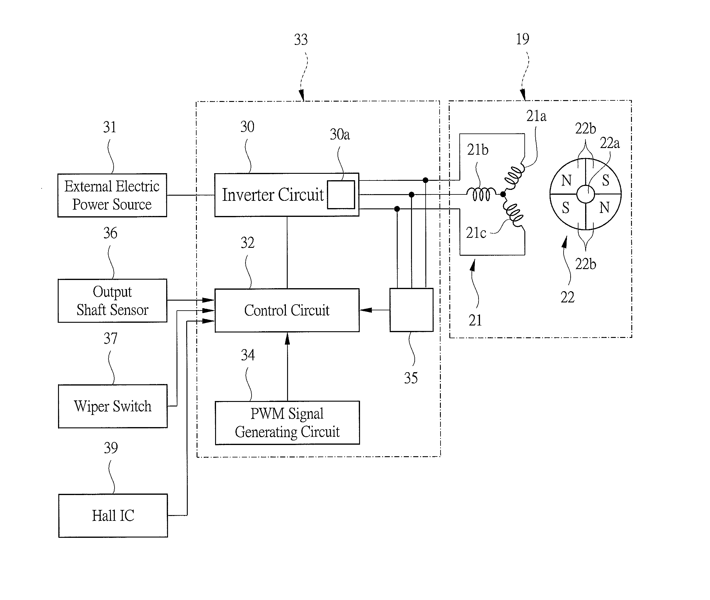
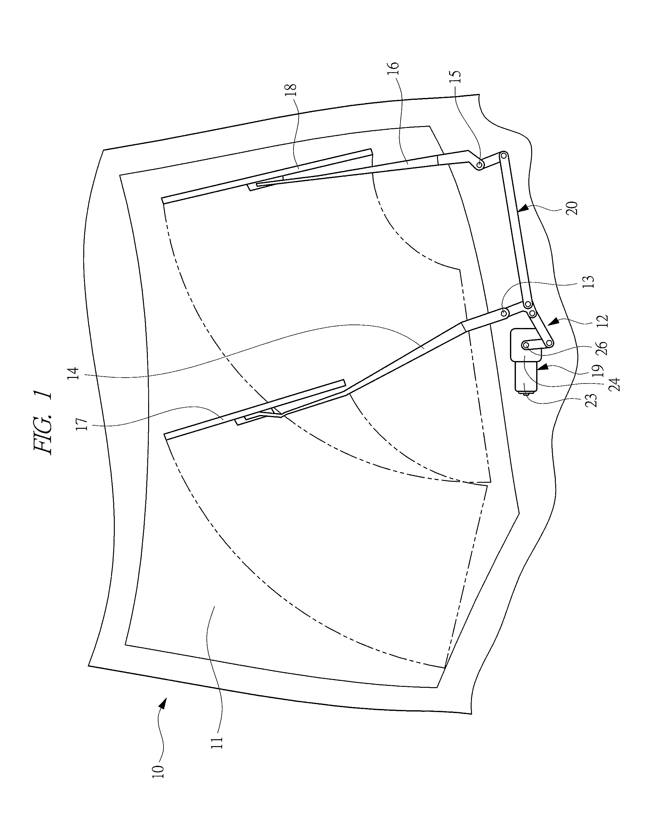
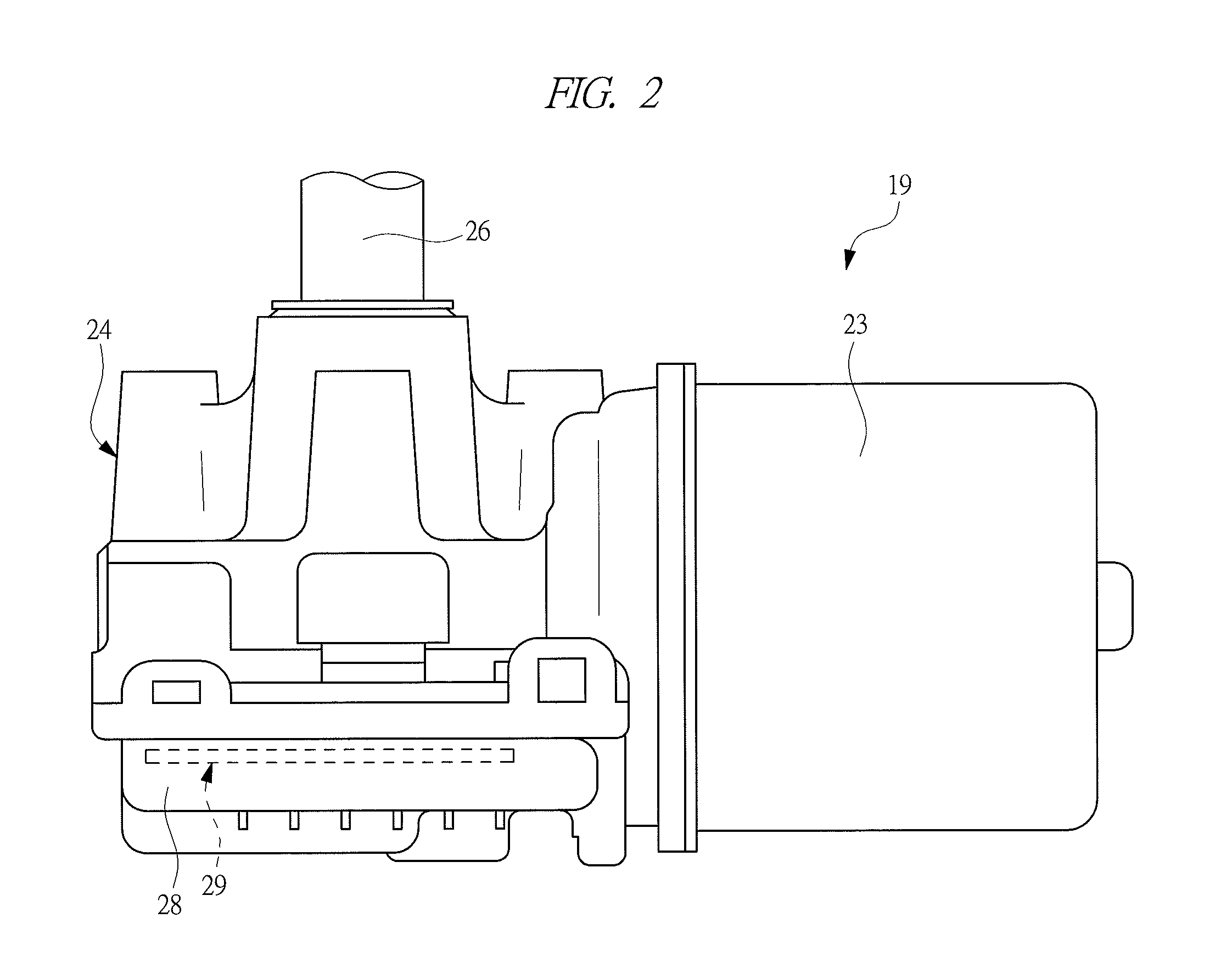
[0046]Hereinafter, an embodiment of the present invention will be described in detail with reference to the drawings. A vehicle 10 shown in FIG. 1 has a windshield 11. The vehicle 10 further has a wiper apparatus 12 for wiping the windshield 11. The wiper apparatus 12 has: a wiper arm 14 which swings on a pivot shaft 13; and a wiper arm 16 which swings on a pivot shaft 15. A wiper blade 17 is mounted on a free end of the wiper arm 14, and a wiper blade 18 is mounted on a free end of the wiper arm 16. The wiper apparatus 12 further has a brushless motor 19 as a drive power source for driving the wiper arms 14 and 16. In this embodiment, the drive power of the brushless motor 19 is transmitted to the wiper arms 14 and 16 via a drive power transmission mechanism 20 composed of parts such as levers and links.

[0047]The brushless motor 19 is constructed as shown in FIGS. 2, 3 and 4. A three-phase four-pole brushless motor 19 is employed as the brushless motor 19 in this embodiment. The br...


PUM


Abstract

A brushless motor comprises: a stator 21 having armature coils 21a, 21b, and 21c; a rotor 22 which is rotated by a revolving magnetic field; and a switching element 30a, wherein the brushless motor has a rotation number control unit 33 which switches between low-speed and high-speed mode, wherein in the low-speed mode, the rotation number control unit 33 supplies current to the armature coils 21a, 21b, and 21c at predetermined energization timing and controls a duty ratio to control the rotation number of the rotor 22, and in the high-speed mode, the rotation number control unit 33 supplies current to the armature coils 21a, 21b, and 21c at energization timing advanced from the energization timing for the low-speed mode, thereby performing field weakening control of weakening the revolving magnetic field from that of the low-speed mode to control the rotation number of the rotor 22.

Description

CROSS REFERENCE TO RELATED APPLICATION[0001]Applicant hereby claims foreign priority benefits under U.S.C. §119 from Japanese Patent Application No. JP2012092882 filed on Apr. 16, 2012 and from Japanese Patent Application No. JP2013036019 filed on Feb. 26, 2013, and from PCT / JP2013 / 061336 filed on Apr. 16, 2013 the contents of all of which are incorporated by reference herein.TECHNICAL FIELD[0002]The present invention relates to a brushless motor having: a rotor mounted with permanent magnets; and a stator provided with an armature coil, and a wiper motor.BACKGROUND ART[0003]Conventionally, examples of a motor in which the rotation number of a rotor is switchable are disclosed in Japanese Patent Application Laid-Open Publication Nos. JP2007202391, JP2007143278, and JP201093977. The motor described in Japanese Patent Application Laid-Open Publication Nos. JP2007202391 and JP2007143278 has a case, a magnet accommodated in the case, an armature rotatably provided inside the case and ha...

Claims


Application Information

Patent Timeline
Patent Type & Authority Applications(United States)
IPC IPC(8): H02P6/14B60S1/16B60S1/08H02P6/08H02P6/22
CPCH02P6/145H02P6/08B60S1/166B60S1/08H02P6/22H02P6/182H02P23/009H02P2207/05H02K11/215H02P6/153B60S1/0818B60S1/0896B60S1/26H02K7/1166H02P6/16
Inventor KIMURA, MASAAKITANAKA, HIROTOIWAZAKI, TAMOTSUANNAKA, TOMOHIKOKOJIMA, NAOKIKITAZAWA, JUNYA
Owner MITSUBA CORP
Why Eureka
Try Eureka